Multi-stage thermodynamic water supply equipment

A technology of water supply equipment and thermal power, applied in the field of multi-stage thermal water supply equipment, can solve the problems of high inlet water temperature, high condensation temperature of refrigeration system, high condensation temperature, etc., achieve high precision of water temperature control, high comfort of use, and reduce environmental pollution Effect

Inactive Publication Date: 2017-03-15
史静
View PDF0 Cites 0 Cited by
  • Summary
  • Abstract
  • Description
  • Claims
  • Application Information

AI Technical Summary

Problems solved by technology

[0002] At present, heat pump water heaters are used to prepare domestic hot water, and centralized storage and supply of hot water are widely used. However, traditional domestic hot water storage and supply systems use single-stage water storage for hot water preparation, storage and supply. The single-stage water storage cannot realize the stratification of cold and hot water because the internal water bodies are fused together
Due to heat transfer and mixing problems, although there is cold water replenishment in the lower part of the water tank, after the cold water replenishment enters the water tank, it is mixed and heat transferred by the hot water stored in the water tank, which will cause the condensation temperature of the refrigeration system of the heat pump water heater to be very high. Due to the characteristics of the refrigeration cycle, the higher the condensation temperature, the lower the energy efficiency of the refrigeration system, resulting in a rather low operating efficiency of the heat pump water heater unit
It can be seen that the current traditional single-stage water storage domestic hot water storage and supply system cannot naturally stratify the hot water and cold water temperatures, resulting in high water inlet temperature, high condensation temperature, low efficiency, and high energy consumption of the heat pump water heater unit.

Method used


Image

  • Multi-stage thermodynamic water supply equipment

Examples


Embodiment 1

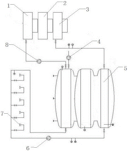
[0013] This embodiment provides a multi-stage thermal water supply equipment, characterized in that: the multi-stage thermal water supply equipment includes a primary heat pump (1), a secondary heat pump (2), a tertiary heat pump (3), and a supplementary water pump ( 4), multi-stage heat storage device (5), hot water supply pump (6), hot water use terminal (7), heating circuit pump (8);

[0014] Among them: the primary heat pump (1), the secondary heat pump (2) and the tertiary heat pump (3) form a hot water heating unit, through the supplementary water pump (4) and the heating circuit pump (8) and the multi-stage heat storage device (5) The other end of the multi-stage heat storage device (5) is connected to the hot water use terminal (7).

[0015] A control valve is provided between the hot water heating unit consisting of a primary heat pump (1), a secondary heat pump (2) and a tertiary heat pump (3) and the multi-stage heat storage device (5), and the multi-stage heat stor...


PUM


Abstract

The invention provides multi-stage thermodynamic water supply equipment. The multi-stage thermodynamic water supply equipment is characterized by comprising a first-stage heat pump, a second-stage heat pump, a third-stage heat pump, a water replenishing pump, a multi-stage heat reservoir, a hot water supply water pump, a hot water using terminal and a heating loop water pump, wherein the first-stage heat pump, the second-stage heat pump and the third-stage heat pump form a hot water heating unit; the hot water heating unit is connected with the multi-stage heat reservoir through the water replenishing pump and the heating loop water pump; and the other end of the multi-stage heat reservoir is connected with the hot water using terminal. The multi-stage thermodynamic water supply equipment provided by the invention has the advantages of realizing natural layering of temperature of the hot water and cold water according to a temperature gradient by adopting a multi-stage type domestic hot water storage and supply method, realizing full utilization of energy and being high in efficiency, low in energy consumption, reasonable in design, high in water temperature control precision, stable in output water temperature, high in use comfort and capable of reducing environmental pollution.

Description

technical field [0001] The invention relates to the technical field of hot water storage and water supply systems, in particular to a multi-stage thermal water supply equipment. Background technique [0002] At present, heat pump water heaters are used to prepare domestic hot water, and centralized storage and supply of hot water are widely used. However, traditional domestic hot water storage and supply systems use single-stage water storage for hot water preparation, storage and supply. The single-stage water storage cannot realize the stratification of cold and hot water because the internal water bodies are fused together. Due to heat transfer and mixing problems, although there is cold water replenishment in the lower part of the water tank, after the cold water replenishment enters the water tank, it is mixed and heat transferred by the hot water stored in the water tank, which will cause the condensation temperature of the refrigeration system of the heat pump water h...

Claims


Application Information

Patent Timeline
IPC IPC(8): F24D17/02
Inventor 史静
Owner 史静
Why Eureka
Try Eureka