
Stirring apparatus for producing coatings

A technology of stirring device and coating, which is applied to mixers with rotary stirring devices, accessories of mixers, transportation and packaging, etc., can solve the problems of low stirring efficiency and long stirring time, and achieve high efficiency, large gaps, and reduced material mixing. Effects of Probability of Foreign Substances

Pending Publication Date: 2017-03-15
CHONGQING ALL COLOR WORLD COATING CO LTD
View PDF7 Cites 4 Cited by
  • Summary
  • Abstract
  • Description
  • Claims
  • Application Information

AI Technical Summary

Problems solved by technology

[0004] The present invention intends to provide a stirring device for coating production to solve the problem that in the prior art, the materials fall into a relatively fixed area and are separated before stirring, resulting in a long stirring time and low stirring efficiency. low problem

Method used


Image

  • Stirring apparatus for producing coatings
  • Stirring apparatus for producing coatings
  • Stirring apparatus for producing coatings

Examples


Embodiment 1

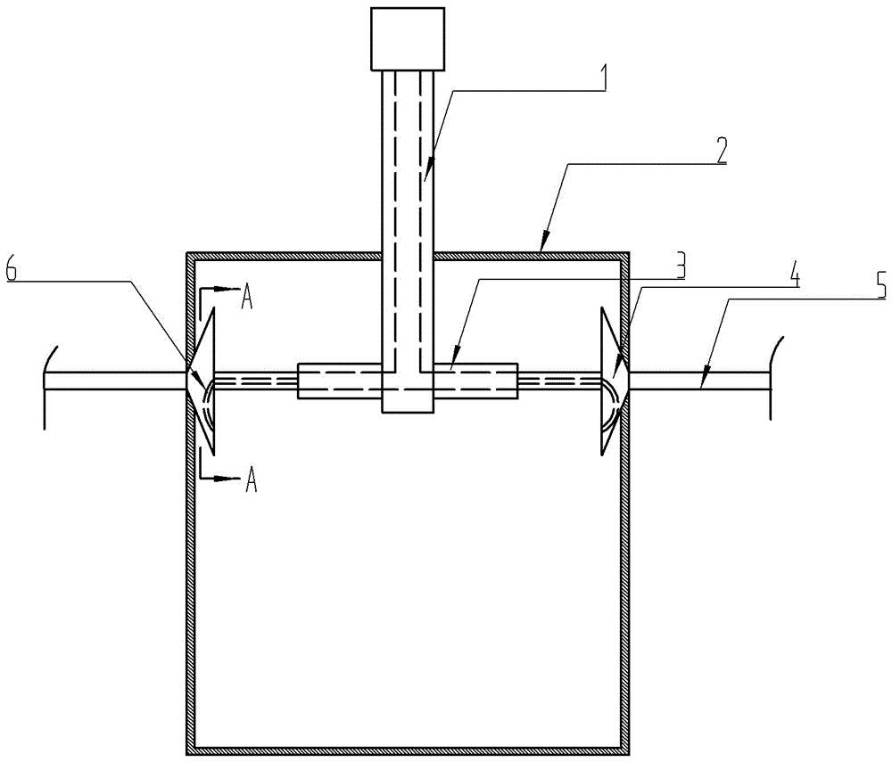
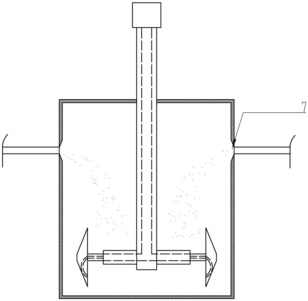
[0028] The stirring device that is used for coating production in embodiment 1, as figure 1 As shown, it includes a housing 2, a stirring shaft 1, and a stirring beam 3 vertically fixed to the stirring shaft 1. The stirring shaft 1 extends into the housing 2 and can be driven by a power mechanism to rotate and reciprocate up and down; the stirring beam 3 The middle part of the stirring shaft 1 is welded on one end of the housing 2, and the stirring beam 3 is perpendicular to the stirring shaft 1; the stirring beam 3 is a hollow sleeve that can be driven by another power mechanism to expand and contract; A stirring part 4 is respectively installed symmetrically around the stirring shaft 1;

[0029] The longitudinal section of the stirring part 4 is trapezoidal, and one side of the long side of the stirring part 4 is connected with the end of the stirring beam 3, and the housing 2 is provided with two through holes 7, which are connected with the respective ends of the two stirr...

Embodiment 2

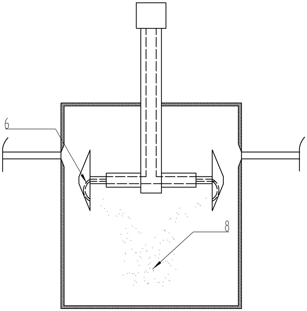
[0036]In this embodiment, the difference from Embodiment 1 is that the stirring part 6 is set as a trapezoidal cover in longitudinal section, supported on the stirring beam 3 by a bracket, and the stirring part 6 does not have an oblique through hole 9;

[0037] The material 8 is directly ejected from the stirring beam 3 and is blocked by the stirring part 6, and the material falls into the shell 2 more dispersedly under the impact.


PUM


Abstract

The invention discloses a stirring apparatus for producing coatings. The stirring apparatus comprises a housing and a stirring shaft extended into the housing, and also comprising a stirring cross beam perpendicularly fixed to the stirring shaft; the stirring cross beam is a hollow sleeve driven by a power mechanism to telescope; an end of the stirring cross beam is also provided with a stirring portion; the vertical section of the stirring portion is trapezoidal, one long side of the stirring portion is connected to the end of the stirring cross beam, the housing is provided with a through hole mating with one short side of the stirring portion, the stirring shaft is of hollow tubular structure and is communicated with the stirring cross beam that is also of hollow tubular structure, the stirring portion is also internally provided with a discharge passage, and the stirring shaft, the stirring cross beam and the discharge passage are communicated to form a passage allowing material to pass through; the discharge end of the discharge passage is positioned at the lower half of the long side of the stirring portion and is inclined close to the housing. The stirring apparatus has the advantages that material is pre-dispersed, stirring efficiency is improved, and coating production efficiency is improved.

Description

technical field [0001] The invention relates to the technical field of paint processing, in particular to a stirring device for paint production. Background technique [0002] The coating production process is usually as follows: first, pre-mix and disperse the powdery raw materials in the tank (dissolver) with a disperser, and then manually transport the dispersed materials to a sand mill for fine grinding and other reprocessing. And according to production needs, it can be further stirred and finely dispersed by the mixer, and then the material is transported to the filter device by the pump for filtration, and the filtered material can be filled by the filling machine for the final finished product. [0003] The existing mixer feeds through fixed feed inlets or feed channels before mixing, and the materials fall in a relatively fixed area and are separated before mixing, which leads to a longer mixing time , stirring efficiency is low. Contents of the invention [000...

Claims


Application Information

Patent Timeline
Patent Type & Authority Applications(China)
IPC IPC(8): B01F7/18B01F15/02
CPCB01F27/054B01F27/0725B01F27/092B01F27/112B01F27/81B01F27/806B01F27/90B01F35/717B01F35/7547B01F2101/30
Inventor 梁知荣
Owner CHONGQING ALL COLOR WORLD COATING CO LTD
Learn More