Two-stage type flue gas cleaning system for garbage incinerator

A flue gas purification system and waste incinerator technology, applied in gas treatment, chemical instruments and methods, dispersed particle filtration, etc., can solve problems such as heat loss and increased energy consumption, and achieve the effect of reducing energy loss and improving purification efficiency

Inactive Publication Date: 2017-03-15
SHENZHEN ENERGY ENVIRONMENT ENG
View PDF4 Cites 18 Cited by
  • Summary
  • Abstract
  • Description
  • Claims
  • Application Information

AI Technical Summary

Problems solved by technology

[0005] In order to solve the problems of the existing waste incinerator flue gas treatment system, in order to increase the flue gas temperature, it is necessary to install a heat exchanger at the tail, resulting in heat loss and increasing energy consumption. Dust removal system, rearrange the SCR and the original flue gas treatment system, set the selective catalytic reduction device SCR after the first-stage bag filter and before the lime slurry preparation system and semi-dry reaction tower, so that the flow through the selective catalytic reduction device The flue gas temperature of the SCR meets the requirements and meets the working conditions of the SCR, so there is no need to install a heat exchanger to save energy

Method used


Image

  • Two-stage type flue gas cleaning system for garbage incinerator
  • Two-stage type flue gas cleaning system for garbage incinerator

Examples


Embodiment Construction

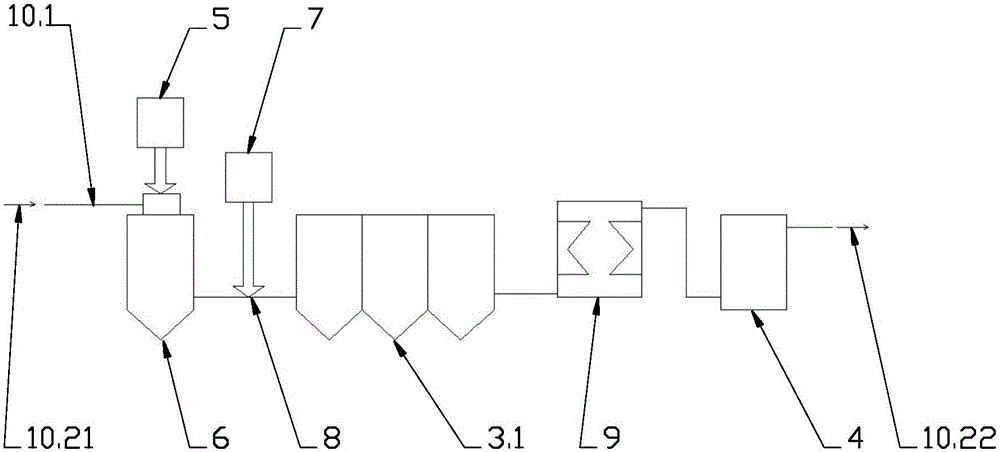
[0022] figure 1 It is a device layout diagram of an embodiment of the prior art. The figure shows that in the prior art, the flue gas purification system installed in the flue gas pipeline of the waste incinerator is sequentially composed of a lime slurry preparation system 5 and a semi-dry reaction tower (rotary atomizer) according to the direction of flue gas flow. 6. Activated carbon storage and delivery system 7. Activated carbon injection system 8. First-stage bag filter 3.1. Heat exchanger 9. Selective catalytic reduction device (SCR) 4. As shown in the figure, the waste incinerator flue gas purification system needs to install a heat exchanger 9 at the front end of the selective catalytic reduction (SCR) 4. The reason is that since the working temperature of the SCR is about 200°C, After flowing in from the flue gas pipe 10.1 according to the flue gas inflow direction 10.21, it enters the semi-dry reaction tower 6 and passes through the lime slurry rotary sprayer. The ...


PUM


Abstract

In order to solve the problems such as heat loss and energy consumption increase caused by the fact that a heat exchanger needs to be additionally mounted at the tail of an existing garbage incinerator flue gas treatment system to increase the temperature of flue gas, the invention provides a two-stage type flue gas cleaning system for a garbage incinerator. The two-stage type flue gas cleaning system is characterized by comprising a sodium bicarbonate dry process deacidifying system, a sodium bicarbonate injection system, a primary bag-type dust collector, a selective catalytic reducer SCR, a lime slurry preparation system, a half-dry type reaction tower (rotary atomizer), an active carbon storage conveying system, an active carbon storage injection system and a secondary bag-type dust collector in sequence according to a flue gas flowing direction. Due to the fact that the selective catalytic reducer SCR is arranged beside the primary bag-type dust collector and in front of the lime slurry preparation system and the half-dry type reaction tower, the temperature of flue gas is not reduced, and the inlet temperature condition of the selective catalytic reducer SCR is fully met, a heat exchanger does not need to be mounted at the front end of the SCR, and the energy loss is reduced.

Description

technical field [0001] The invention relates to a flue gas purification device of a garbage incinerator, in particular to a two-stage flue gas purification system of a garbage incinerator. Background technique [0002] At present, the waste incineration power plant incinerator flue gas treatment system uses the selective non-catalytic reduction method in the furnace to remove nitrogen oxides (NOx) in the flue gas, and then removes the nitrogen oxides (NOx) in the flue gas by semi-dry method and activated carbon injection plus bag filter. Other harmful substances such as particulate matter, sulfur oxides (SOx), dioxins, and heavy metals. [0003] However, with the increasingly stringent laws and regulations related to environmental protection, the existing waste incineration power plant flue gas treatment system can no longer meet the requirements of laws and regulations, and it is necessary to install a selective catalytic reduction device on the flue gas pipe outside the fu...

Claims


Application Information

Patent Timeline
Patent Type & Authority Applications(China)
IPC IPC(8): B01D53/81B01D53/83B01D53/86B01D53/80B01D53/50B01D53/10B01D50/00B01D46/02
CPCB01D53/81B01D46/02B01D50/00B01D53/10B01D53/502B01D53/80B01D53/83B01D53/86B01D2251/304B01D2251/404B01D2251/60B01D2253/102B01D2257/2064B01D2257/60B01D2258/0283B01D2258/0291
Inventor 张辉
Owner SHENZHEN ENERGY ENVIRONMENT ENG
Why Eureka
Try Eureka