DC Motor Unidirectional Driver
A DC motor and driver technology, applied in the electronic field, can solve the problems of mutual influence of the output of the driving circuit and low utilization rate of the device, and achieve the effects of ensuring the control function and circuit reliability, improving the utilization rate, and simplifying the circuit design.
- Summary
- Abstract
- Description
- Claims
- Application Information
AI Technical Summary
Problems solved by technology
Method used
Image

Examples
Embodiment 1
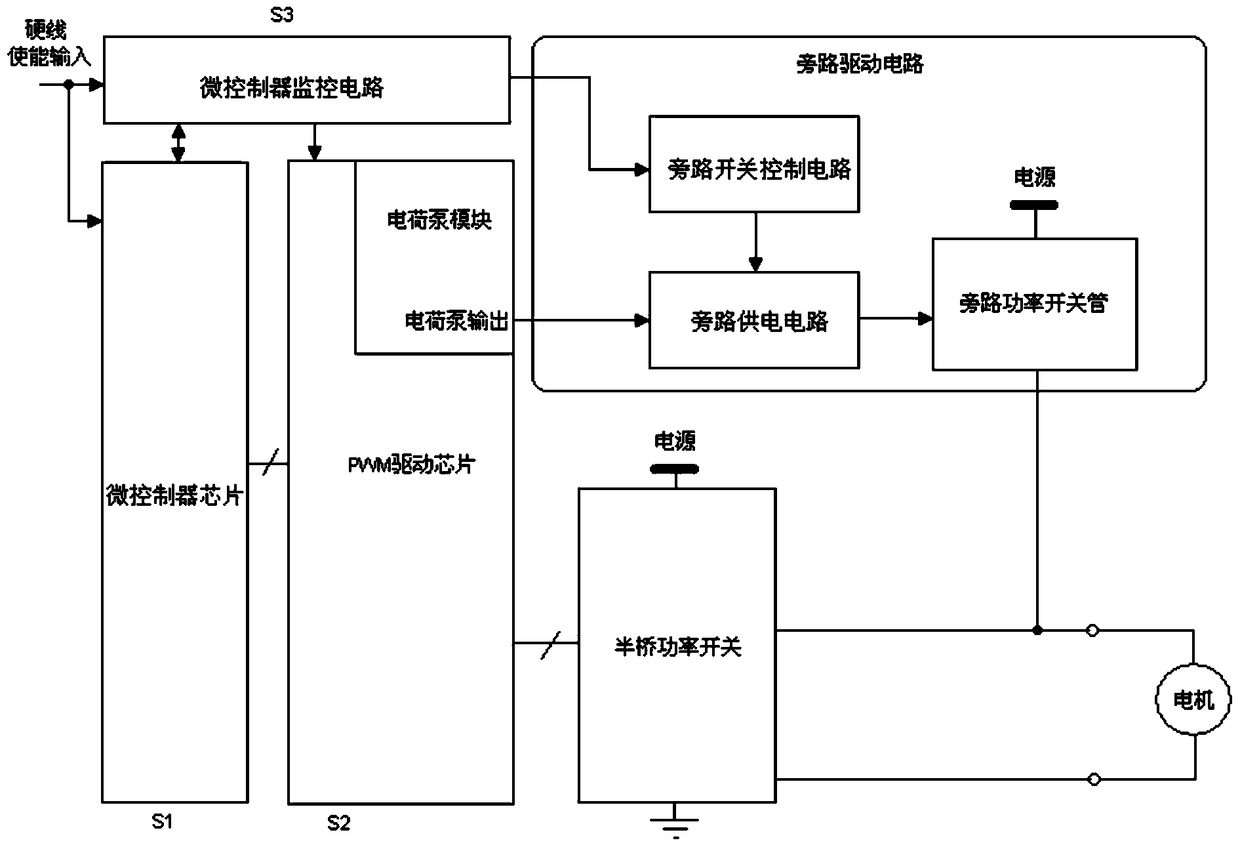
[0035] DC motor unidirectional drives such as figure 1 As shown, it includes a microcontroller chip S1, a PWM driver chip S2, a microcontroller monitoring circuit S3, a power switch circuit, and a bypass drive circuit;
[0036] The bypass drive circuit includes a bypass switch control circuit, a bypass power supply circuit, and a bypass power switch tube;
[0037] The bypass switch control circuit is used to control the opening and closing of the bypass power supply circuit;
[0038] The bypass power supply circuit is used to provide a turn-on voltage for the bypass power switch tube;
[0039] The bypass power switch tube is connected to the DC motor at the output end;
[0040] The power switch circuit is connected to a DC motor at the output end;
[0041] The PWM driver chip S2 has an independent charge pump module;
[0042] In the independent charge pump module, the voltage output terminal VPUMP is connected to the bypass power supply circuit of the bypass drive circuit;...
Embodiment 2
[0051] Based on the unidirectional DC motor driver of Embodiment 1, the bypass power switch tube adopts a MOSFET (Metal-Oxide Semiconductor Field Effect Transistor) with over-current and over-temperature protection functions.
[0052] Preferably, the power switch circuit is a half-bridge power switch circuit.
[0053] Preferably, the microcontroller chip S1 controls the PWM driving chip S2 to output a driving signal through an internal bus.
[0054] Preferably, the PWM driver chip S2 adopts a multi-mode high-frequency PWM controller UCC39421 / 2.
[0055] In the DC motor unidirectional driver of the second embodiment, the bypass power switch tube of the bypass drive circuit adopts a MOSFET with over-current and over-temperature protection functions, and even in the bypass drive mode, it still has the output anti-short circuit and over-current functions .
Embodiment 3
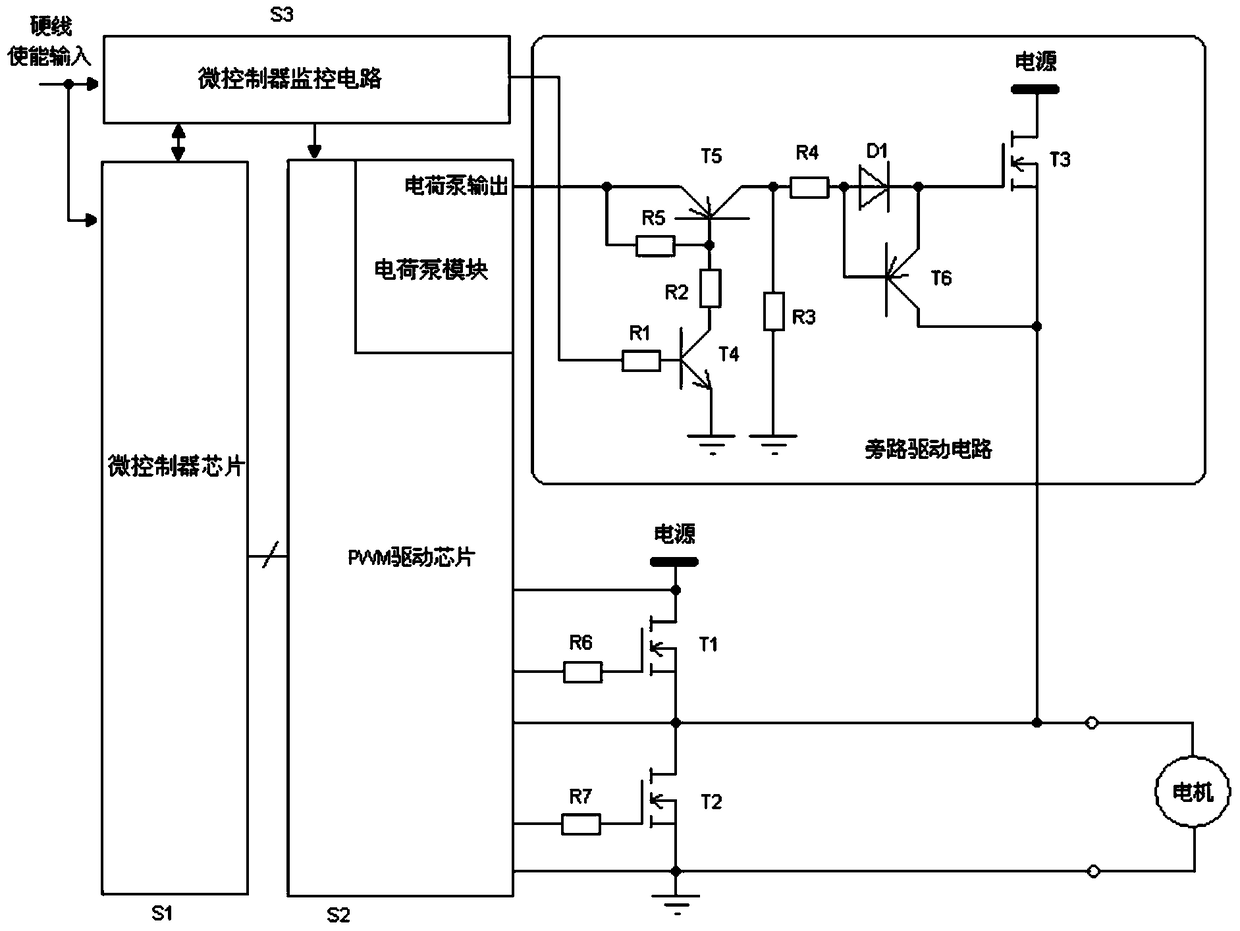
[0057] Based on the DC motor unidirectional driver of Embodiment 1, such as figure 2 As shown, the bypass drive circuit includes a first resistor R1, a second resistor R2, a third resistor R3, a fourth resistor R4, a fifth resistor R5, a fourth transistor T4, a fifth transistor T5, The sixth transistor T6, the third power transistor T3, and the diode D1;
[0058] The enable signal output by the microcontroller monitoring circuit S3 is connected to the base of the fourth transistor T4 through the first resistor R1;
[0059] The emitter of the fourth transistor T4 is grounded, and the collector is connected to the base of the fifth transistor T5 through the second resistor R2;
[0060] The emitter of the fifth transistor T5 is connected to the voltage output terminal VPUMP of the independent charge pump module of the PWM driver chip S2; the collector is connected to the base of the sixth transistor T6 through the fourth resistor R4;
[0061] The third power tube T3 is an N-ty...
PUM
 Abstract
Description
Claims
Application Information
 - R&D
- Intellectual Property
- Life Sciences
- Materials
- Tech Scout
- Unparalleled Data Quality
- Higher Quality Content
- 60% Fewer Hallucinations
Browse by: Latest US Patents, China's latest patents, Technical Efficacy Thesaurus, Application Domain, Technology Topic, Popular Technical Reports.
© 2025 PatSnap. All rights reserved.Legal|Privacy policy|Modern Slavery Act Transparency Statement|Sitemap|About US| Contact US: help@patsnap.com