W-ti sputtering target

A sputtering target and target surface technology, applied in sputtering coating, vacuum evaporation coating, coating and other directions, can solve the problems of etching speed variation, inability to perform uniform etching, etc., and achieve the effect of small etching speed

Active Publication Date: 2017-02-22
MITSUBISHI MATERIALS CORP
View PDF5 Cites 5 Cited by
  • Summary
  • Abstract
  • Description
  • Claims
  • Application Information

AI Technical Summary

Problems solved by technology

[0012] However, as mentioned above, the etching rate is improved by adding a small amount of Fe to the W-Ti film, but if the Fe concentration of the W-Ti film varies, the etching rate will locally change in the W-Ti film, Thus, uniform etching may not be possible

Method used


Image

  • W-ti sputtering target
  • W-ti sputtering target
  • W-ti sputtering target

Examples


Embodiment

[0067] Hereinafter, the result of the evaluation test which evaluated the function effect of the W-Ti sputtering target concerning this invention is demonstrated.

[0068]

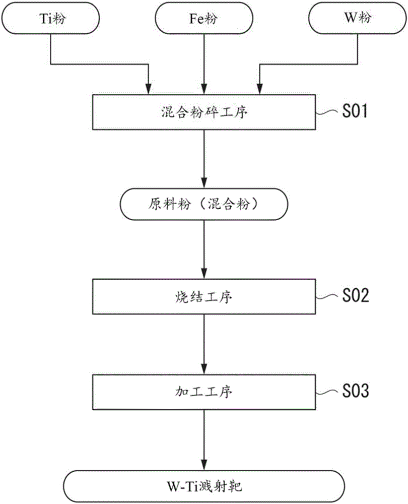
[0069] As raw material powders, Ti powder with a purity of 99.999% by mass and an average particle size of 15 μm, W powder with a purity of 99.999% by mass and an average particle size of 1 μm, and Fe powder with a purity of 99.999% by mass and an average particle size of 100 μm were prepared. And Ti powder, Fe powder, and W powder were weighed so that it might become the composition shown in Table 1.

[0070] Among the weighed Ti powder, Fe powder, and W powder, the W powder and Fe powder were put into an attritor device (MA1D of NIPPON COKE & ENGINEERING CO., LTD.) together with cemented carbide balls with a diameter of about 5 mm, and the Mixing and pulverization was performed for 1 hour under an Ar atmosphere at a rotational speed of 300 ppm. In addition, in order to prevent the mixing of impurities...


PUM

PropertyMeasurementUnit
particle sizeaaaaaaaaaa

Abstract

This W-Ti sputtering target has a composition containing Ti in a range of 5% by mass to 20% by mass and Fe in a range of 25 ppm by mass to 100 ppm by mass, the remainder comprising W and unavoidable impurities, and satisfies the relational expression (Femax-Femin) / (Femax+Femin) <= 0.25, where Femax is the maximum value of the Fe concentration and Femin is the minimum value of the Fe concentration when the Fe concentration is measured in a plurality of locations in the plane of the target.

Description

technical field [0001] The present invention relates to a W-Ti sputtering target in which a W-Ti film is formed between a bump and a ground electrode used for mounting a semiconductor element, for example, as a diffusion prevention layer for preventing mutual element diffusion. [0002] This application claims priority based on Patent Application No. 2014-207343 for which it applied in Japan on October 8, 2014, and uses the content here. Background technique [0003] Conventionally, when mounting a semiconductor chip on a substrate, for example, Au bumps or solder bumps are formed on Al electrodes or Cu electrodes. [0004] Here, for example, when the Al electrode is in direct contact with the Au bump, an intermetallic compound between Al and Au is formed due to mutual diffusion of Al and Au, which may increase resistance or decrease adhesion. Furthermore, for example, when the Cu electrode is in direct contact with the solder bump, intermetallic compounds between Cu and Sn...

Claims


Application Information

Patent Timeline
Patent Type & Authority Applications(China)
IPC IPC(8): C23C14/34B22F5/00C22C27/04B22F3/14
CPCB22F3/14B22F5/00C22C27/04C23C14/34C23C14/3414
Inventor 野中庄平斋藤淳大友健志
Owner MITSUBISHI MATERIALS CORP
Why Eureka
Try Eureka