
Method for reducing harmonic distortion in comb drive devices

a technology of harmonic distortion and comb drive, which is applied in the direction of electrostatic generator/motor, generator/motor, and semiconductor/solid-state device details, etc., can solve the problems that the relative small etch buffer placed between adjacent fingers of the comb drive structure may be difficult to remove during final wafer dissolution, and achieve uniform etch rate, reduce the effect of relative large gaps and reduce the difference in etch ra

Inactive Publication Date: 2005-06-23
HONEYWELL INT INC
View PDF7 Cites 4 Cited by
  • Summary
  • Abstract
  • Description
  • Claims
  • Application Information

AI Technical Summary

Benefits of technology

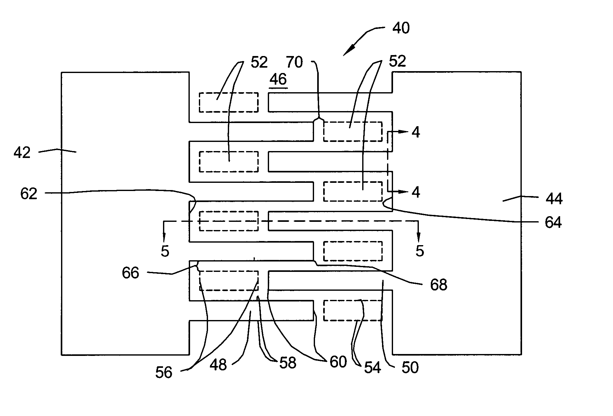
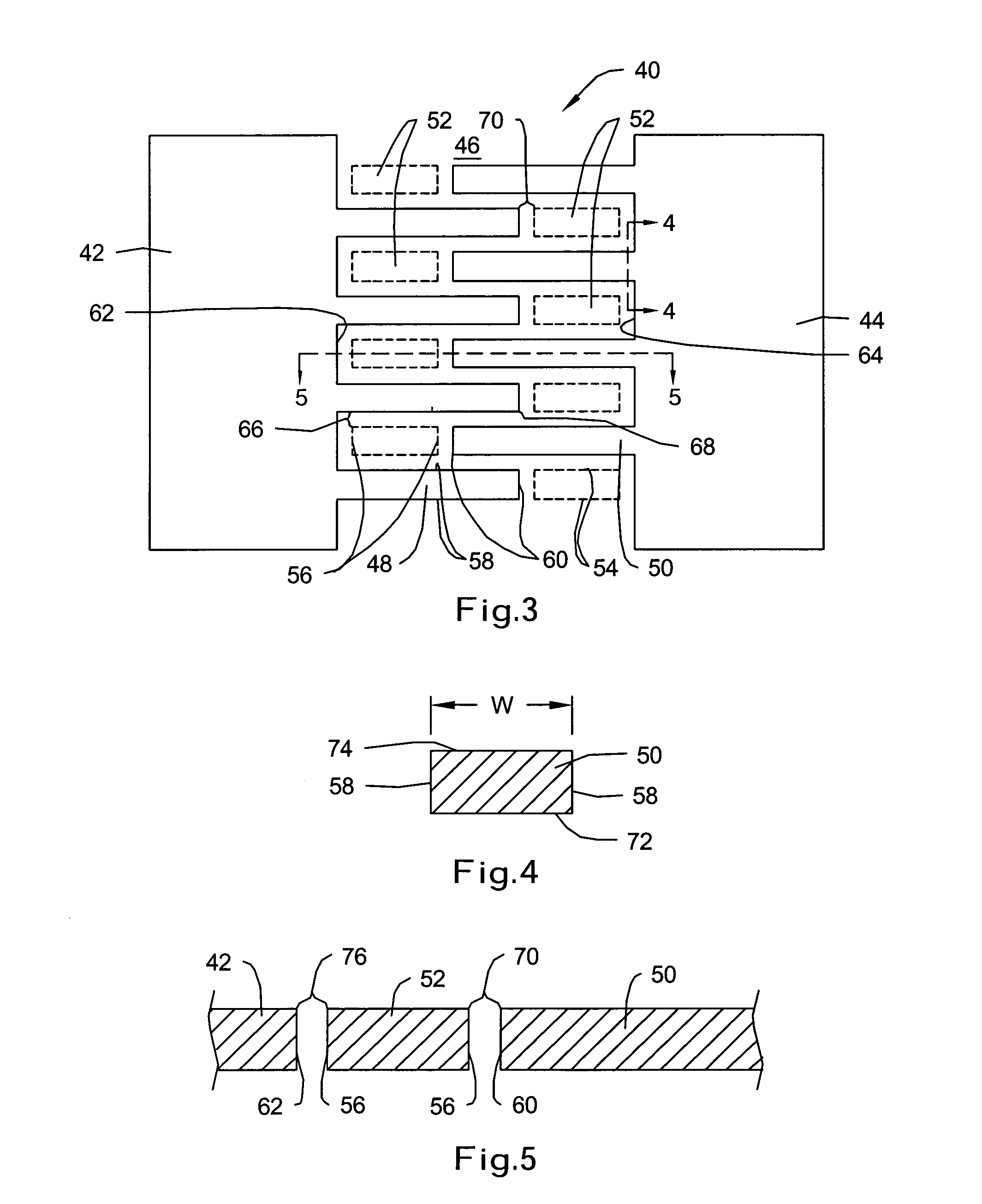
[0006] The present invention relates to fabrication methods for reducing harmonic distortion in comb drive devices. In an illustrative method of the present invention, an epitaxial layer of, for example, highly boron-doped (p++) silicon or other suitable material can be grown or formed on the surface of a wafer substrate used to form an electrostatic comb drive device. A patterned mask layer defining a number of comb drive elements and one or more sacrificial etch-buffers can be formed on the p++layer. Etch-buffers can be employed to make the gap between adjacent features more uniform. These etch-buffers can be used at or near those locations where producing a uniform etched profile is desirable. In some cases, the etch-buffers can be relatively small in size, such as when positioned between adjacent fingers of a comb drive structure. In other cases, the etch-buffers can be larger in size, such as when it is also desirable to fill in area that does not need to be etched. The pattern can be etched into the p++ layer and through to the underlying substrate.
[0009] When employed, the sacrificial etch-buffers may act to reduce or eliminate the relatively large gaps between non-overlapping regions of the comb drive fingers. The etch-buffers can be formed at selective regions on the wafer substrate to ensure a relatively uniform etch rate along the length and / or at the ends of the comb fingers. In certain embodiments, for example, the sacrificial etch-buffers can be used to provide a uniform gap between the sides of adjacent comb fingers. During etching, this uniform gap may reduce differences in etch rates that can occur along the length of the comb fingers, thus providing a more uniform profile to the comb fingers. As a result, the capacitive force induced as the comb fingers move with respect to each other tends to be more linear, which may substantially reduce the introduction of electrical harmonics into the drive system.

Problems solved by technology

In some cases, the relatively small etch-buffers that are placed between adjacent fingers of a comb drive structure may be difficult to remove during final wafer dissolution.

Method used


Image

  • Method for reducing harmonic distortion in comb drive devices
  • Method for reducing harmonic distortion in comb drive devices
  • Method for reducing harmonic distortion in comb drive devices

Examples


Embodiment Construction

[0016] The following description should be read with reference to the drawings, in which like elements in different drawings are numbered in like fashion. The drawings, which are not necessarily to scale, depict selected embodiments and are not intended to limit the scope of the invention. Although examples of construction, dimensions, and materials are illustrated for the various elements, those skilled in the art will recognize that many of the examples provided have suitable alternatives that may be utilized.

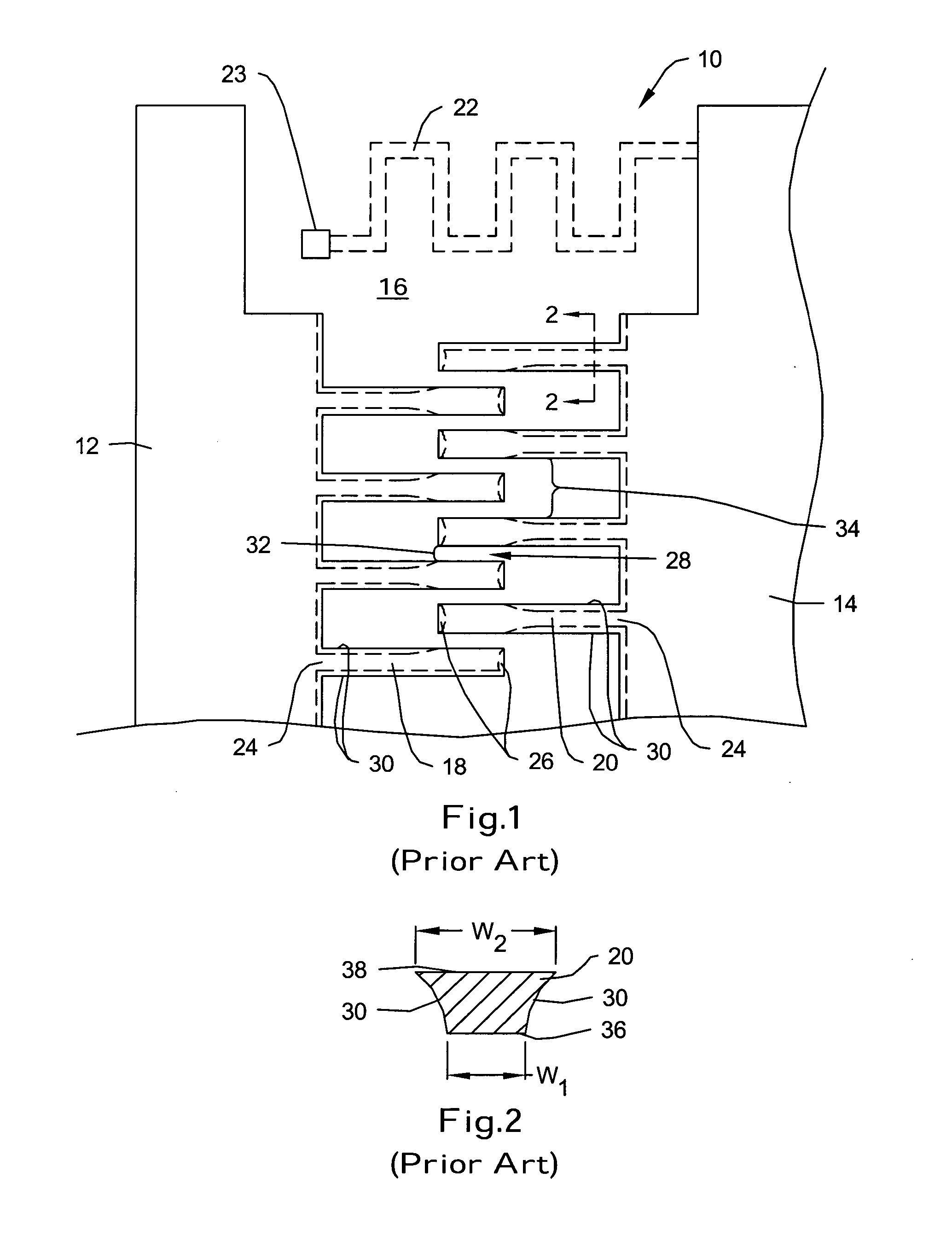
[0017]FIG. 1 is a schematic view of an illustrative prior art electrostatic comb drive device 10 including a number of comb drive elements having a non-uniform profile. Comb drive device 10, illustratively a linear comb drive device, includes first and second comb drive members 12,14 each formed in an opposing manner over a glass support substrate 16. While a glass support substrate 16 is used, it is contemplated that the support substrate 16 may be made from any suitable ma...


PUM


Abstract

Methods of fabricating comb drive devices utilizing one or more sacrificial etch-buffers are disclosed. An illustrative fabrication method may include the steps of etching a pattern onto a wafer substrate defining one or more comb drive elements and sacrificial etch-buffers, liberating and removing one or more sacrificial etch-buffers prior to wafer bonding, bonding the etched wafer substrate to an underlying support substrate, and etching away the wafer substrate. In some embodiments, the sacrificial etch-buffers are removed after bonding the wafer to the support substrate. The sacrificial etch-buffers can be provided at one or more selective regions to provide greater uniformity in etch rate during etching. A comb drive device in accordance with an illustrative embodiment can include a number of interdigitated comb fingers each having a more uniform profile along their length and / or at their ends, producing less harmonic distortion during operation.

Description

FIELD OF THE INVENTION [0001] The present invention relates generally to the field of semiconductor manufacturing and microelectromechanical systems (MEMS). More specifically, the present invention pertains to fabrication methods for reducing harmonic distortion in comb drive devices. BACKGROUND OF THE INVENTION [0002] Electrostatic comb drive devices are utilized to provide movement or motion in microelectromechanical systems (MEMS) devices. Such drive devices are employed, for example, in the fabrication of MEMS-type accelerometers, gyroscopes, and inertia sensing devices where rapid actuation is often necessary to effectively measure and / or detect motion and acceleration. [0003] In a typical comb drive device, a main body is supported over an underlying support substrate using a number of anchors. One or more drive elements electrically coupled to the main body can be actuated to manipulate the main body above the support substrate in a particular manner. In certain designs, for ...

Claims


Application Information

Patent Timeline
Patent Type & Authority Applications(United States)
IPC IPC(8): B81B3/00H02N1/00
CPCB81B2201/0271B81C2201/0132B81C1/00698B81B2201/033
Inventor RIDLEY, JEFFREY A.NEUS, JAMES A.
Owner HONEYWELL INT INC
Learn More