Layered piston connecting rod assembly

A technology of piston connecting rod and connecting rod assembly, which is applied to pistons, engine components, machines/engines, etc., can solve the problems of low melting point of aluminum pistons, broken engines, and inability to share, achieve good thermal and mechanical properties, improve Speed ​​and precision, the effect of solving bottleneck problems

Inactive Publication Date: 2017-02-22
蒙国全
View PDF0 Cites 0 Cited by
  • Summary
  • Abstract
  • Description
  • Claims
  • Application Information

AI Technical Summary

Problems solved by technology

[0005] Secondly, during the installation of the above-mentioned piston and connecting rod assembly, due to workers’ omissions or transfer, vibration, rotation and other reasons during the installation process, the opening directions of the piston rings are likely to overlap, resulting in reduced engine combustion pressure, reduced power torque, and engine oil. Serious situations such as deformation and fracture of piston rings, abnormal engine noise, and cylinder scuffing
[0006] Finally, aluminum (including aluminum alloy and aluminum-based composite materials, etc.) pistons are light in weight and have low inertia, which is beneficial to reduce the overall weight of the engine and increase the maximum speed of the engine. However, the aluminum piston has a low melting point and its hardness is greatly affected by temperature, so it is not suitable for It is used in high-torque, high-load engines (such as diesel engines). Although cast iron and cast steel pistons have high hardness and high melting point, they are not suitable for high-speed, lightweight engines (such as gasoline engines) due to their overall bulkiness and high inertia. use on
The two piston technologies cannot be shared, which doubles the cost of R&D, manufacturing, packaging and transportation for enterprises

Method used


Image

  • Layered piston connecting rod assembly
  • Layered piston connecting rod assembly
  • Layered piston connecting rod assembly

Examples


Embodiment Construction

[0036]The embodiments of the present invention will be described in detail below in conjunction with the accompanying drawings, so that the advantages and features of the present invention can be more easily understood by those skilled in the art, so as to define the protection scope of the present invention more clearly.

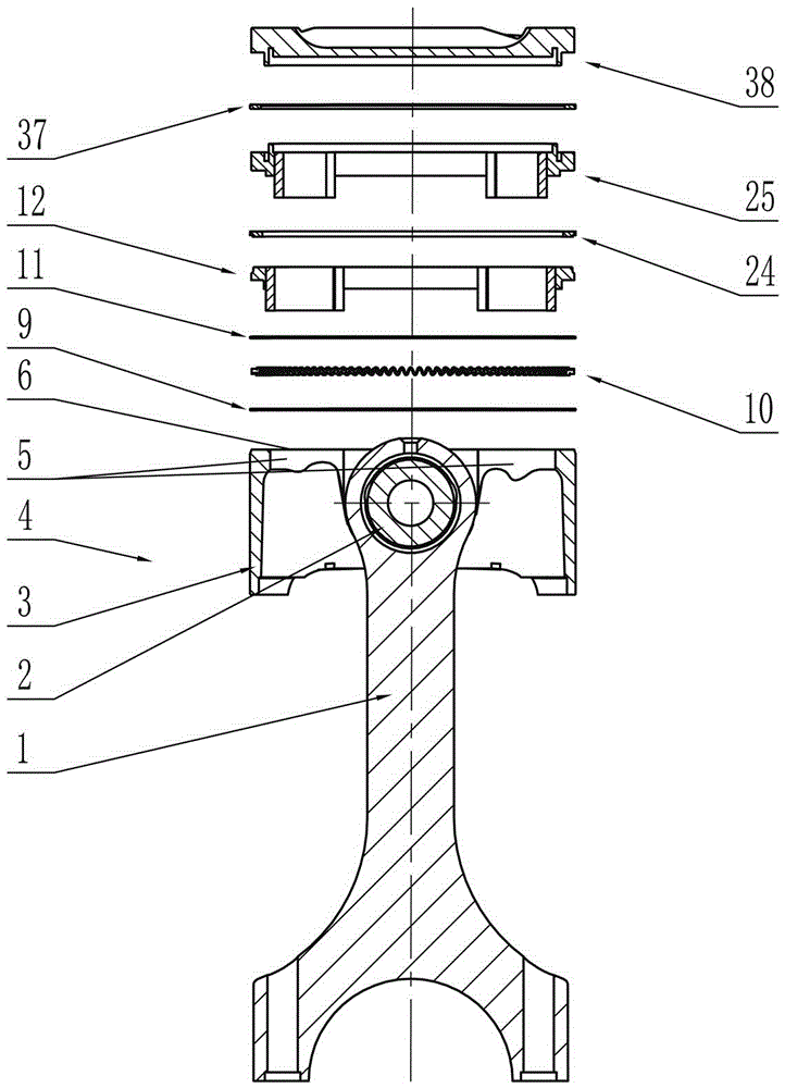
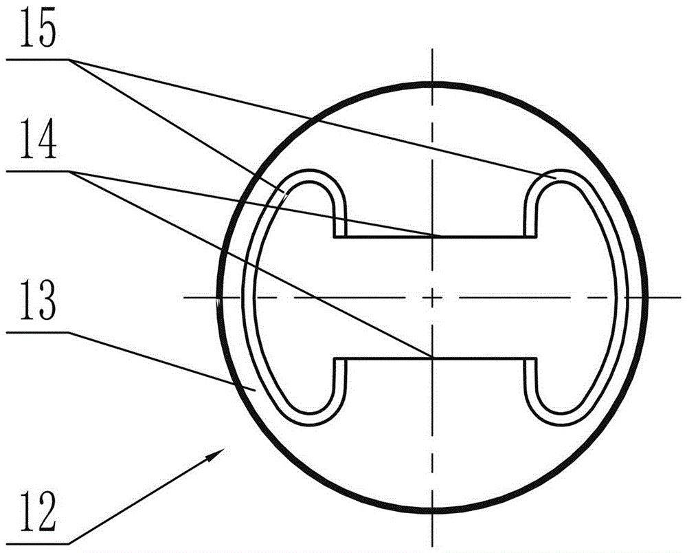
[0037] Such as figure 1 As shown, the piston skirt connecting rod assembly 4 is assembled by the connecting rod 1, the piston pin 2 and the piston skirt 3, the mechanical structure and installation process of the connecting rod 1 and the piston pin 2 still use the existing technology, and the inner wall of the piston skirt 5 It is a smooth cylindrical surface, which intersects with the piston skirt top surface 6 to form a figure 2 From the two "C"-shaped lines 7 shown symmetrical to the axis of the piston pin 2, it can be deduced that the inner wall 5 of the piston skirt is two "C"-shaped cylindrical surfaces.

[0038] Such as figure 2 As shown, the two...


PUM


Abstract

The invention discloses a layered piston connecting rod assembly. The piston connecting rod assembly is formed by mounting a piston skirt connecting rod assembly (4), a lower scraper (9), a lining ring (10), an upper scraper (11), a lower piston head (12), a second gas ring (24), a middle piston head (25), a first gas ring (37) and an upper piston head (38) in a cylinder hole (48) of a cylinder body (47) in sequence. A middle piston skirt (3), a lower piston head body (13) and a middle piston head body (26) use aluminum alloys or aluminum base composite materials; and the upper piston head (38) uses a cast iron or cast steel material. The piston connecting rod assembly can realize full-automatic installation and cylinder entering by equipment and automatic control of opening directions of the piston gas rings and the scrapers, and still can keep lower weight under the precondition of excellent thermal and mechanical performances.

Description

technical field [0001] The invention relates to an engine component, in particular to a layered piston connecting rod assembly. Background technique [0002] At present, the piston and connecting rod assembly on the engine is composed of main parts such as piston, connecting rod, piston pin, combined oil ring and gas ring, among which the piston is manufactured by complex processes such as machining and surface treatment after integral casting. Its structure is usually divided into two parts, the piston skirt and the piston head, in which the piston skirt is responsible for the hinge connection with the connecting rod and plays the role of power transmission; the piston head has a piston ring groove, a piston ring land and a piston top surface (including Combustion chamber) and other structures. The piston ring (including combined oil ring, second gas ring and first gas ring) is installed in the piston ring groove, and its displacement in the piston axial direction is restr...

Claims


Application Information

Patent Timeline
Patent Type & Authority Applications(China)
IPC IPC(8): F02F3/00B23P21/00
CPCF02F3/0015B23P21/002
Inventor 蒙国全
Owner 蒙国全
Why Eureka
Try Eureka