A kind of enameled wire tray installation method and its tray installation mechanism

A technology of installation mechanism and installation method, which is applied in the directions of transportation and packaging, thin material handling, and delivery of filamentous materials, etc. It can solve the problems of easy toppling of trays, troubles, and inaccurate positioning of trays, etc., to achieve fully automated installation Effect

Active Publication Date: 2022-02-11
WUXI JUYI TONGCHUANG TECH CO LTD
View PDF16 Cites 0 Cited by
  • Summary
  • Abstract
  • Description
  • Claims
  • Application Information

AI Technical Summary

Problems solved by technology

After use, some defects were found. Grabbing the tray from the outside is often unstable, and the tray is easy to fall when placed; moreover, because the placement of the tray cannot be positioned accurately, the limit hole of the tray cannot be matched with the limit hole of the tray. If the positioning column is precisely matched, the bottom of the plate will be uneven, and the platen equipment will not be able to accurately press the center hole of the plate, let alone take up the wire evenly. When the plate is not placed in place, manual intervention is required. Automated manufacturing

Method used


Image

  • A kind of enameled wire tray installation method and its tray installation mechanism
  • A kind of enameled wire tray installation method and its tray installation mechanism
  • A kind of enameled wire tray installation method and its tray installation mechanism

Examples


Embodiment Construction

[0028] The present invention will be further described below in combination with specific embodiments.

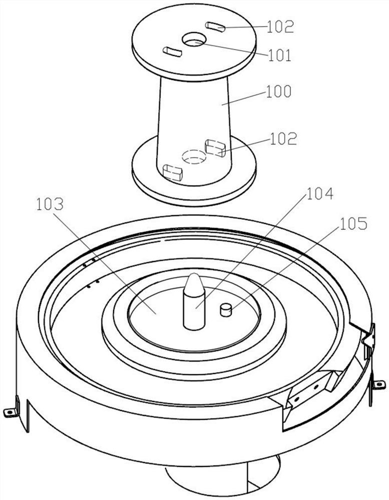
[0029] The center of the tray 100 has a central hole 101, and the bottom of the tray has a limit hole 102. After the tray 100 is placed in place, the enameled wire can be wound up in an orderly manner.

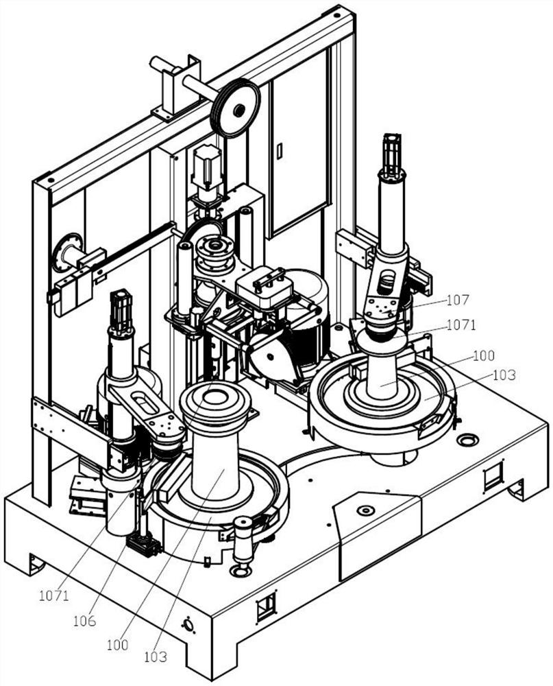
[0030] Such as figure 1 As shown, the present invention provides a method for installing an enameled wire tray. This method is used in the process of placing the empty tray 100 to ensure that the tray 100 is installed in place. The method includes the following steps:

[0031] Step ①: lifting the tray 100: Insert the hanging tray device 106 into the central hole 101 of the tray 100 to lift the tray 100, and move the tray 100 to the top of the tray 103;

[0032] Step ②: put down the tray 100: place the tray 100 on the upper surface of the tray 103, release the tray 100 by the hanging tray device 106, and place the hanging tray device 106 in the central hole 101 of the tray ...


PUM


Abstract

The invention discloses an enameled wire tray installation method and its tray installation mechanism. The tray installation method includes steps ① lifting the tray, step ② putting down the tray, step ③ rotating the tray, positioning the tray, and step ④ removing the tray Hanging plate equipment, step ⑤ presses the plate; the plate installation mechanism includes the tray, the hanging plate equipment and the pressure plate equipment. The center of the tray is provided with a central axis, and the upper surface of the tray is provided with a limit column. Slightly smaller than the hole diameter of the center hole of the pan, the limit column can be accommodated in the limit hole of the pan, the hanging plate equipment includes the hanging pan shaft and the hinge block assembly, the hinge block assembly can be extended or retracted on the outer wall of the suspension pan shaft , the outer diameter of the suspension plate shaft is slightly smaller than the aperture of the central hole of the plate, and the platen device includes a platen head, which can press the central hole of the plate from above the plate. By using the installation mechanism and the installation method, no manual intervention is required when the dish is installed, the bottom of the dish can be ensured to be placed stably, and the fully automatic installation of the dish can be realized.

Description

technical field [0001] The invention relates to the field of enameled wire production, and more specifically relates to an enameled wire tray installation method and a tray installation mechanism thereof. Background technique [0002] The enameled wire is composed of the inner wire and the coating that wraps the wire. During the production process of the enameled wire, the wire needs to be wound on the reel by a wire take-up machine. [0003] Before taking up the wire, it is necessary to place the reel on the tray of the wire take-up machine, and press the reel with a platen device, and then start to take up the wire after positioning the upper and lower ends of the reel. At present, some disk installations are performed purely by manual operation, and no automatic operation has been realized. There is also a robot that grabs the tray from the outside of the tray and then places it on the tray. After use, some defects were found. Grabbing the tray from the outside is often...

Claims


Application Information

Patent Timeline
Patent Type & Authority Patents(China)
IPC IPC(8): B65H67/06B65H67/04
CPCB65H67/06B65H67/068B65H67/0417B65H2701/34
Inventor 张伟新蔡麟梁骁军郎宁卡
Owner WUXI JUYI TONGCHUANG TECH CO LTD
Why Eureka
Try Eureka