
Automatic testing method and system for power quality monitoring device

An automatic test system and monitoring device technology, applied in the field of electric power, can solve the problems of low test efficiency, poor accumulation and reuse of test cases, and tediousness, so as to reduce the workload of writing, reduce the workload and debugging time, The effect of improving stability

Active Publication Date: 2019-08-30
CEIEC ELECTRIC TECH
View PDF6 Cites 0 Cited by
  • Summary
  • Abstract
  • Description
  • Claims
  • Application Information

AI Technical Summary

Problems solved by technology

[0004] Defect 1: New device access needs to write driver files according to the protocol, and device access to the automatic test system is cumbersome
[0005] Defect 2: The current automatic test system can only perform accuracy test and protocol test. For the transient function of power quality, transient function, rapid voltage change function, fixed value over-limit function, set value, etc., it is necessary to detect the action value and duration The function of logical correctness and logical correctness can only be manually tested, the test efficiency is low, and the test cases cannot be well accumulated and reused

Method used


Image

  • Automatic testing method and system for power quality monitoring device
  • Automatic testing method and system for power quality monitoring device
  • Automatic testing method and system for power quality monitoring device

Examples


test Embodiment 1

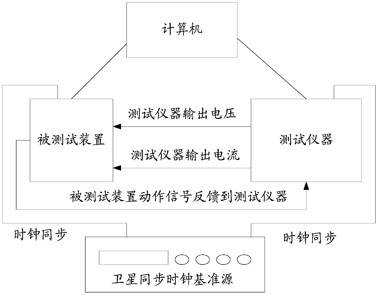
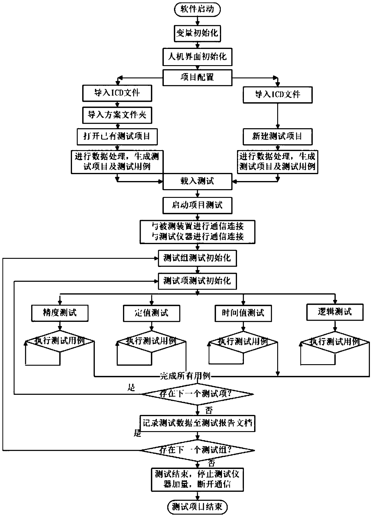
[0085] Test case 1: The output of state sequence 1 is the output frequency 45Hz and the duration is 4s; the output of state sequence 2 is the output frequency 55Hz and the duration is 6s; state sequence 3 and 4 are repetitions of state sequence 1 and 2; Sequences 1 and 2 were cycled 10 times. Starting from state sequence 3 and at the end of each state sequence, the software system reads the frequency of the device under test through the IEC 61850 protocol. The expected result of the preset frequency value is 51Hz, and the allowable error is 0.01Hz.

test Embodiment 2

[0086] Test case 2: The output of state sequence 1 is the output frequency 45Hz, and the duration is 10s. At the end of state sequence 1, the software system reads the frequency of the device under test through the IEC 61850 protocol. The expected result of the preset frequency value is 45Hz, the allowable error is 0.01Hz; the output of state sequence 2 is an output frequency of 55Hz, and the duration is 10s. At the end of state sequence 2, the software system reads the frequency of the device under test. The expected result of the preset frequency value is 55Hz, the allowable error is 0.01Hz; state sequence 1 and 2 are repeated for 10 cycles.

[0087] 2. Import the above test scheme into the software system, and the software system controls the tester to perform incremental output according to the preset state sequence, and in the process, read the frequency value of the device through the IEC61850 protocol, and check it with the expected result set by the user. Thus, the tes...


PUM


Abstract

The invention provides an electric energy quality monitoring device automatic test method and system. An ICD file of the IEC61850 protocol is automatically identified by the test system so that a test case orienting an electric energy quality monitoring device is generated, and comprehensive automatic testing of the electric energy quality monitoring device can be realized. The beneficial effects of the electric energy quality monitoring device automatic test method and system are that the degree of automation of accessing of the electric energy quality monitoring device to the automatic test system can be enhanced, the automatic test process is enabled to be more efficient and stable, the test result is more accurate and reliable, and operation of compiling and modifying the test case is enabled to be flexible and convenient for users by the great human-computer interactive performance design so that the test efficiency of the automatic test system can be enhanced.

Description

technical field [0001] The invention relates to the field of electric power technology, in particular to an automatic testing method and system for a power quality monitoring device. Background technique [0002] With the increase of non-linear loads in the power system, such as harmonics, flicker and voltage fluctuations, three-phase unbalance, voltage deviation, frequency deviation, voltage swell, sag, short interruption, transient events, etc. The power quality problem seriously degrades the power quality of the power grid. At the same time, precision electronic instruments based on computers and microprocessors are widely used in national economic enterprises, and they are becoming more and more sensitive to the quality of power supply. Selective guarantees are made by signing power supply contracts and quality agreements. The power quality monitoring device can accurately detect and analyze the power quality of the power grid, and has the ability to diagnose accidents...

Claims


Application Information

Patent Timeline
Patent Type & Authority Patents(China)
IPC IPC(8): G01R31/00
Inventor 曾幼松林韵婷陈新亮云飞李昊王新华文湘晖李华彬刘云宾杏荣陈力李雪涛潘品陈坚韦颖贾丹丹
Owner CEIEC ELECTRIC TECH
Learn More