A prefabricated concrete urban comprehensive pipe gallery structure and construction method

A comprehensive pipe gallery and prefabricated assembly technology, applied in the direction of basic structure engineering, underwater structures, artificial islands, etc., can solve the problems of high construction cost, difficult construction, and increased water seepage rate of nodes, so as to reduce the construction period and improve Improve construction efficiency and improve the overall effect

Active Publication Date: 2018-08-14
CHANGCHUN INST OF TECH
View PDF7 Cites 1 Cited by
  • Summary
  • Abstract
  • Description
  • Claims
  • Application Information

AI Technical Summary

Problems solved by technology

The emergence of prefabricated prestressed comprehensive pipe gallery, compared with cast-in-place concrete comprehensive pipe gallery, has the advantages of good construction quality, short construction period, and less environmental pollution, but the construction is more difficult
A prefabricated comprehensive pipe gallery widely used at present is to prefabricate the side panels, top panels, bottom panels, and supports separately and assemble them on site. The prestressed steel strand cannot maintain the tension state for a long time, the corrosion resistance and durability need to be solved, and the integrity is poor. Good, poor lateral movement resistance, generally increased water seepage rate at many nodes, high construction cost

Method used


Image

  • A prefabricated concrete urban comprehensive pipe gallery structure and construction method
  • A prefabricated concrete urban comprehensive pipe gallery structure and construction method
  • A prefabricated concrete urban comprehensive pipe gallery structure and construction method

Examples


Embodiment Construction

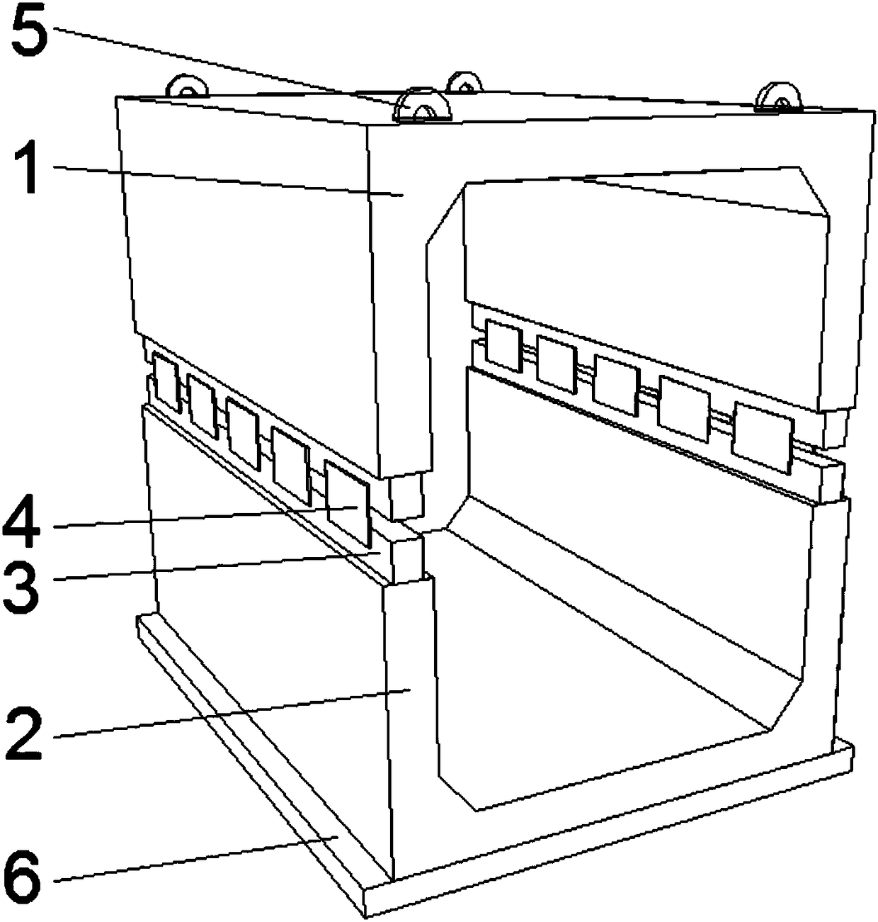
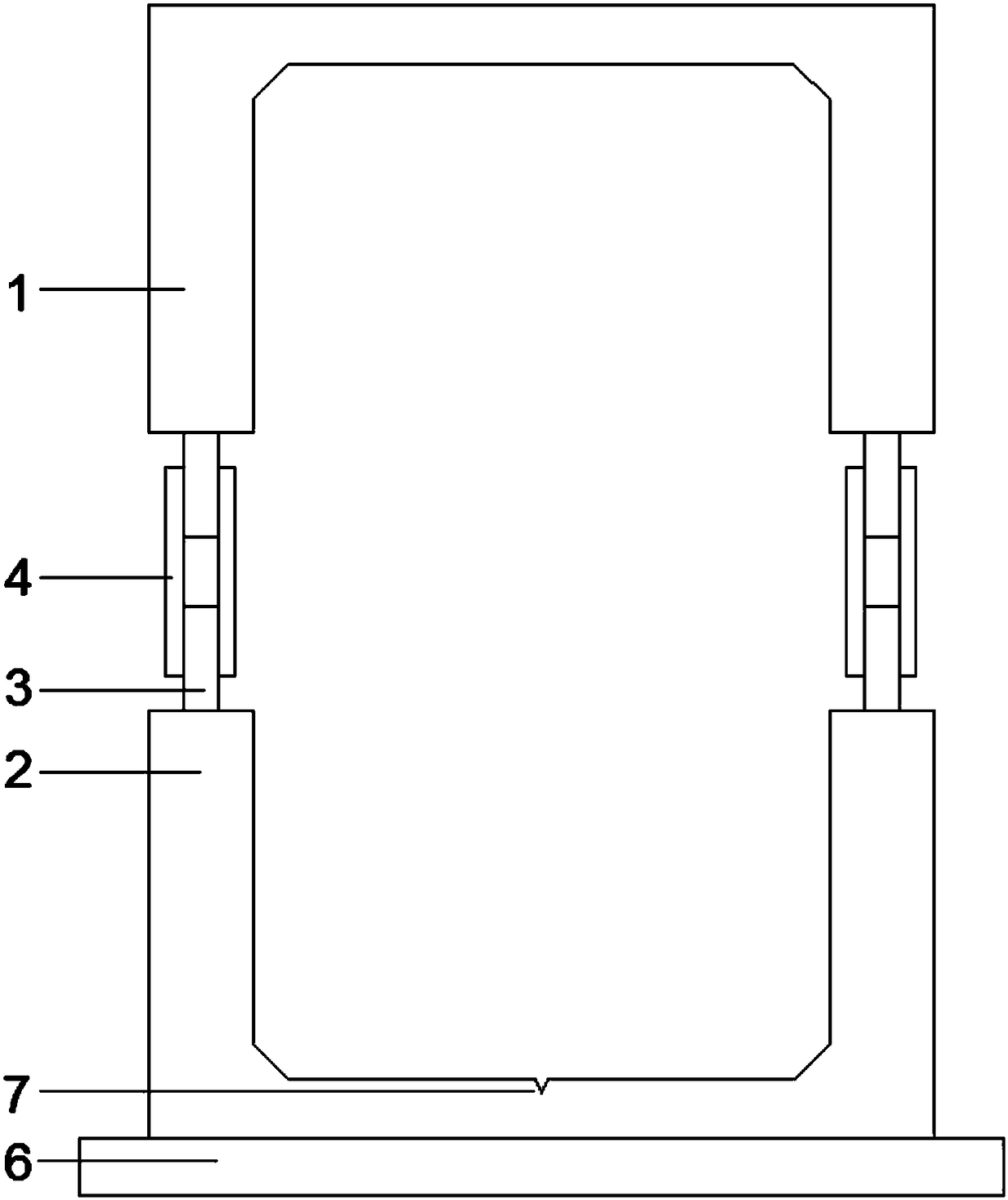
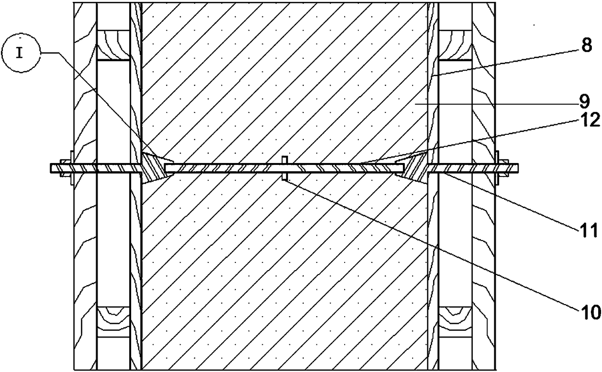
[0022] Refer to attached Figure 1-3 , the specific embodiment of the present invention includes an inverted U-shaped prefabricated pipe gallery 1 on the upper side and a positive U-shaped prefabricated pipe gallery 2 on the lower side, the left and right vertical plates of the positive U-shaped prefabricated pipe gallery and the left and right vertical plates of the inverted U-shaped prefabricated pipe gallery. , the ends of the right vertical plate are respectively embedded with rectangular steel pipes 3, part of the rectangular steel pipes are built-in, and some of the ends of the vertical plate are externally placed. Concrete grouting material, there is a central longitudinal drainage ditch 7 in the middle of the upper surface of the bottom of the U-shaped prefabricated pipe gallery. If the slope is increased in areas with frequent precipitation, four pre-buried Annular lifting lugs 5 are convenient for installation and transportation. When assembling the comprehensive pip...


PUM


Abstract

The invention discloses a prefabricated concrete urban comprehensive pipe rack structure. The prefabricated concrete urban comprehensive pipe rack structure comprises an inverted U-shaped prefabricated pipe rack arranged on the upper side and a straight U-shaped prefabricated pipe rack arranged on the lower side; the two parts are connected through multiple pairs of composed steel plates; bolts for template fixation penetrate through a gap between the upper and lower two parts between two adjacent composed steel plates; a water stop ring is arranged in middle of the steel pipe; the inner side surface of a template is positioned on the positioning surface of tool bolts; the outer side surface of the template is fixedly locked; and the joined gap of the straight U-shaped prefabricated pipe rack and the inverted U-shaped prefabricated pipe rack is filled with expansive cement waterproof concrete. The prefabricated concrete urban comprehensive pipe rack structure adopts the modes of module factory prefabrication and field assembly to improve the construction efficiency and to shorten the construction period. The rectangular steel pipe is arranged at the end part of a vertical plate in the pipe rack connecting place, and is assisted by the composed steel plates to improve the integrity and the sidesway resistance of the structure. The pipe rack connecting place is treated through the waterproof mode of the bolts for template fixation, so that the concrete can be preferably constrained when achieving the water stop effect, and the bearing capacity of the structure is improved.

Description

technical field [0001] The invention relates to the technical field of municipal engineering, in particular to a prefabricated concrete urban comprehensive pipe gallery and a construction method. Background technique [0002] Urban infrastructure construction is a symbol of a city's development. my country's urban construction is following the footsteps of the world, constantly absorbing advanced experience in foreign municipal engineering, and making up for its own shortcomings. The emergence of prefabricated prestressed comprehensive pipe gallery has the advantages of good construction quality, short construction period and low environmental pollution compared with cast-in-place concrete comprehensive pipe gallery, but the construction is more difficult. A prefabricated comprehensive pipe gallery widely used at present is to prefabricate the side panels, top panels, bottom panels, and supports separately and assemble them on site. The prestressed steel strand cannot maint...

Claims


Application Information

Patent Timeline
Patent Type & Authority Patents(China)
IPC IPC(8): E02D29/045
CPCE02D29/045
Inventor 窦立军李恒旭张楠房林福石洋
Owner CHANGCHUN INST OF TECH
Why Eureka
Try Eureka