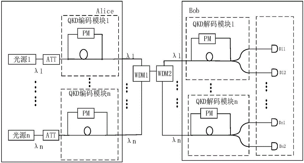
Receiving terminal for quantum key distribution system and quantum key distribution system
A quantum key distribution and receiving end technology, applied in the field of quantum key distribution systems, can solve problems such as unfavorable popularization and application, high system cost, and expensive single-photon detectors, and achieve the effect of reducing cost and improving code rate.
- Summary
- Abstract
- Description
- Claims
- Application Information
AI Technical Summary
Problems solved by technology
Method used
Image
Examples
Embodiment 1
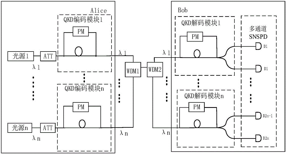
[0041] see figure 2 , the present embodiment is a QKD system based on an array single photon detector, including Alice, a first wavelength division multiplexer (WDM1), a second wavelength division multiplexer (WDM2) and Bob.
[0042] Alice is equipped with QKD encoding module 1 ~ QKD encoding module n, light source 1 ~ light source n, the light emitted by each light source is attenuated to a single photon state by the corresponding attenuator (ATT) and then enters the respective QKD encoding module. Each wavelength corresponds to A QKD encoding module was developed.
[0043] WDM1 multiplexes multiple channels of optical signals of different wavelengths output by each QKD encoding module in Alice into the transmission fiber, WDM2 demultiplexes multiple channels of optical signals of different wavelengths in the transmission fiber To the corresponding QKD decoding module 1~QKD decoding module n in Bob, each decoding module is an unequal arm interference module, which can inter...
Embodiment 2
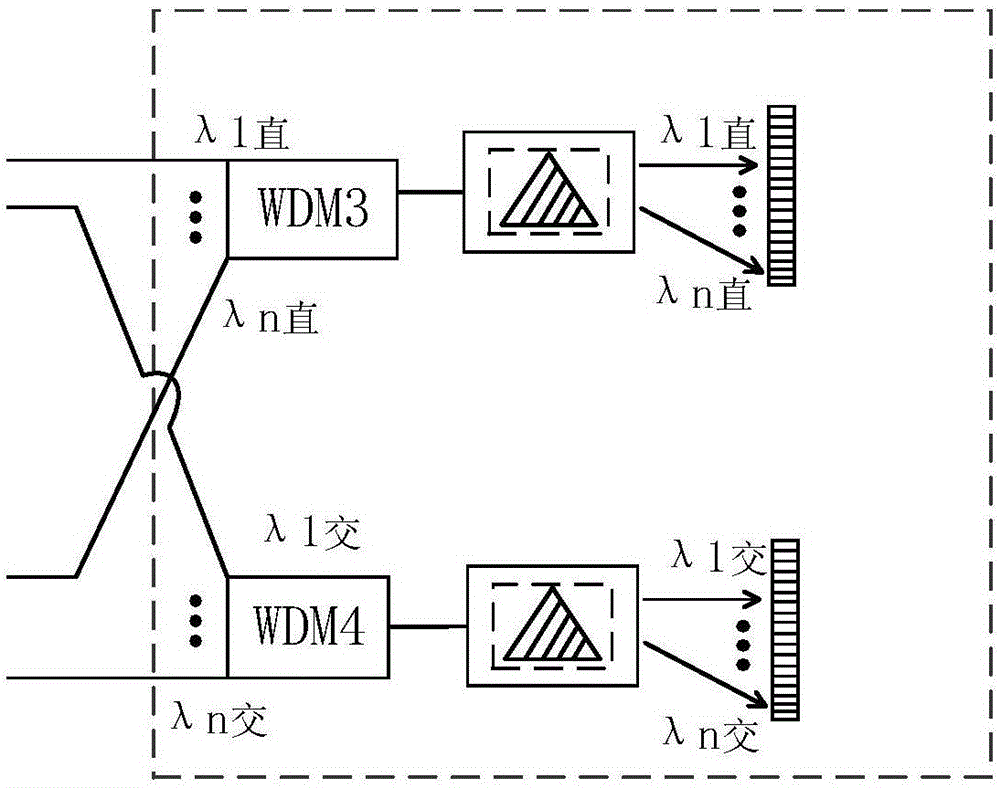
[0047] see image 3 , the present embodiment differs from Embodiment 1 in that a first array detector and a second array detector are provided in the detecting part, and two wavelength division multiplexers (WDM3 and WDM4) and two beam splitters are correspondingly provided module.
[0048] The QKD decoding module corresponding to each wavelength in Bob has two outputs of the straight-through arm and the cross-arm respectively corresponding to two different interference results. The corresponding two outputs of QKD decoding module 1 are recorded as λ1 straight and λ1 intersection. The corresponding two outputs of module n are denoted as λn direct and λn intersecting. Connect the output of the straight-through arm of each QKD decoding module (λ1 straight, λ2 straight...λn straight) to the input of WDM3, and WDM3 multiplexes each wavelength of the straight-through arm into one optical fiber, carrying the multi-wavelength information of the straight-through arm The output end o...
Embodiment 3
[0070] see Image 6 , and the difference from Embodiment 2 is that, after the QKD decoding module in Bob, a densely packed optical fiber array, a microlens array and an array detector are sequentially arranged.
[0071] The QKD decoding module corresponding to each wavelength in Bob has two outputs, a straight-through arm and a cross arm. The output port of the QKD decoding module is connected to the input port of the densely packed optical fiber array. The densely packed optical fiber array is a regular collection of multiple optical fibers. In order to realize the optical elements arranged in a certain order in space, the densely packed optical fiber array has 2N optical fiber input ports and 1 output port, the output port has 2N optical fiber pixels, and the output end of each optical fiber is in the dense A pixel on the output end face of the array of optical fibers, the size and arrangement of the pixels on the output end face of the densely packed optical fiber array are...
PUM
| Property | Measurement | Unit |
|---|---|---|
| Dispersion rate | aaaaa | aaaaa |
Abstract
Description
Claims
Application Information
 - R&D
- Intellectual Property
- Life Sciences
- Materials
- Tech Scout
- Unparalleled Data Quality
- Higher Quality Content
- 60% Fewer Hallucinations
Browse by: Latest US Patents, China's latest patents, Technical Efficacy Thesaurus, Application Domain, Technology Topic, Popular Technical Reports.
© 2025 PatSnap. All rights reserved.Legal|Privacy policy|Modern Slavery Act Transparency Statement|Sitemap|About US| Contact US: help@patsnap.com


