Electromagnetic induction power transfer system
An electric energy transmission system and electromagnetic induction technology, applied in the field of energy transmission, can solve the problems of loss of electromagnetic energy, low energy utilization rate, large magnetic flux leakage, etc.
- Summary
- Abstract
- Description
- Claims
- Application Information
AI Technical Summary
Problems solved by technology
Method used
Image
Examples
Embodiment 1
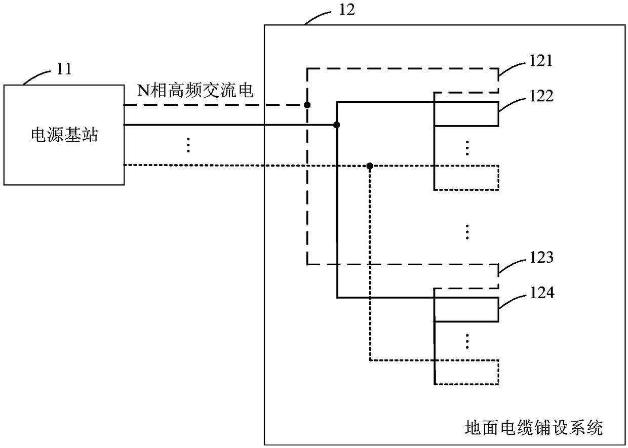
[0021] figure 1 It is a schematic structural diagram of the electromagnetic induction power transmission system provided by Embodiment 1 of the present invention. Such as figure 1 As shown, the electromagnetic induction power transmission system provided in this embodiment may include: a power base station 11 , and a ground cable laying system 12 electrically connected to the power base station 11 .
[0022] The power supply base station 11 is used to convert the power input into the power supply base station 11 into N-phase high-frequency alternating current, and output the N-phase high-frequency alternating current to the ground cable laying system 12 . Wherein, N is greater than or equal to 2.
[0023] The ground cable laying system 12 includes M wire rings surrounded by cables. The number of wire rings with different power supply phases is equal and N wire rings with different power supply phases form a wire ring group. The N wire rings in each wire ring group Lay accor...
Embodiment 2
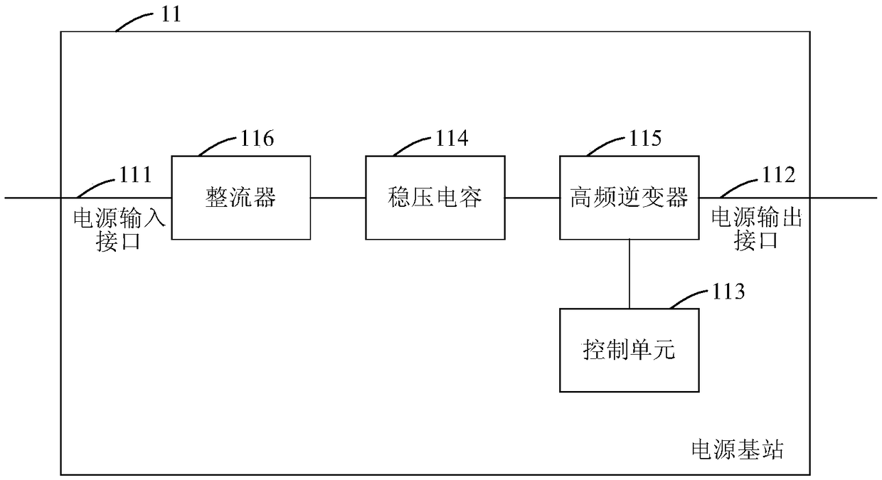
[0037] figure 2 The structure schematic diagram of the electromagnetic induction power transmission system provided by Embodiment 2 of the present invention. On the basis of Embodiment 1, this embodiment provides another implementation of the electromagnetic induction power transmission system, especially the power supply in Embodiment 1. A specific implementation manner of the base station 11. Such as figure 2 As shown, in the electromagnetic induction power transmission system provided in this embodiment, the power base station 11 may include: a power input interface 111 , a power output interface 112 , a control unit 113 , a voltage stabilizing capacitor 114 and a high frequency inverter 115 .
[0038] The power input interface 111 is electrically connected to the voltage stabilizing capacitor 114 , and the high frequency inverter 115 is electrically connected to the voltage stabilizing capacitor 114 , the control unit 113 and the power output interface 112 respectively....
Embodiment 3
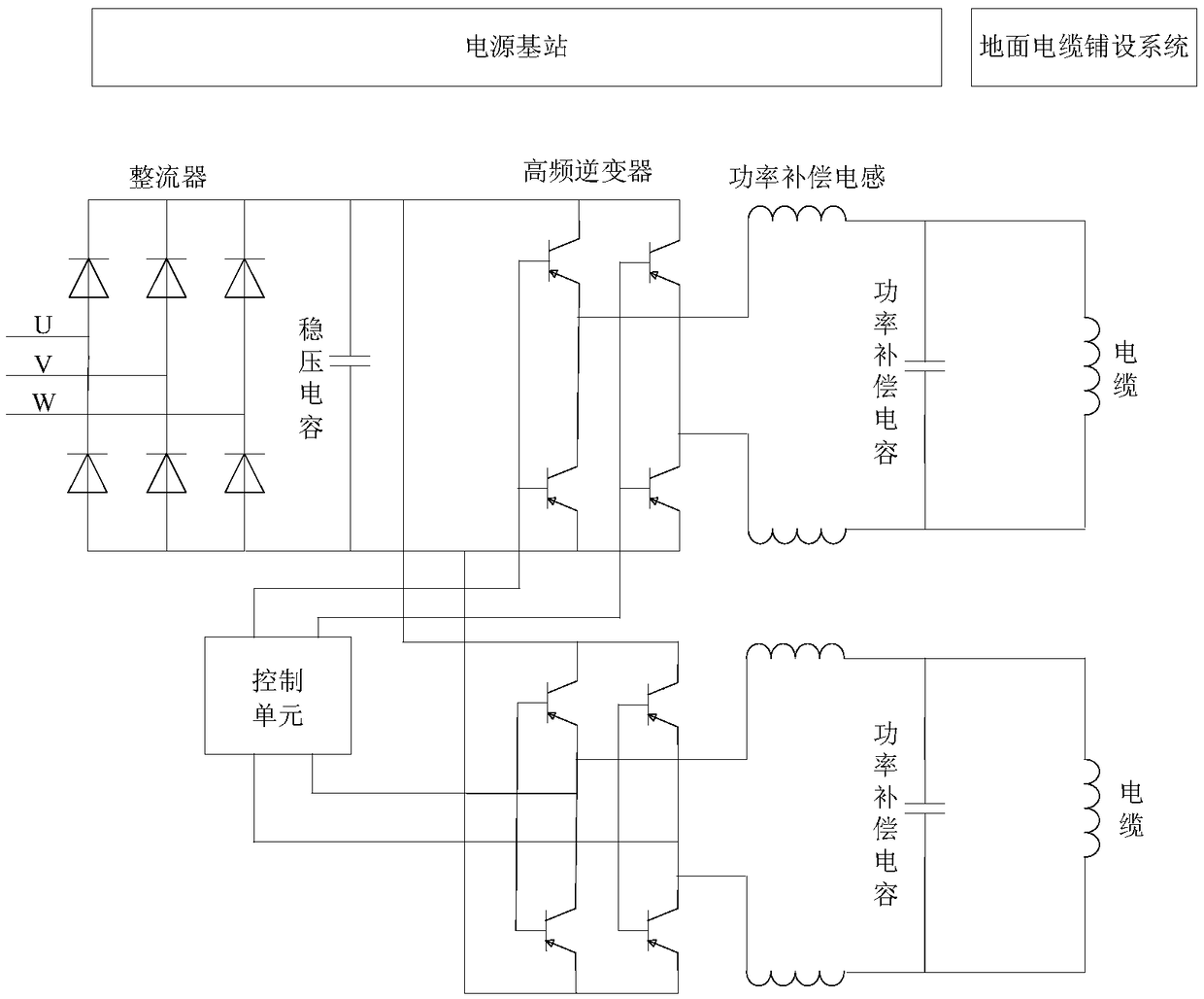
[0087] Figure 3A A schematic structural diagram of the power base station in the electromagnetic induction power transmission system provided by Embodiment 3 of the present invention, Figure 3B It is a schematic structural diagram of the ground cable laying system in the electromagnetic induction power transmission system provided by Embodiment 3 of the present invention. This embodiment provides a specific implementation of the electromagnetic induction power transmission system on the basis of the first and second embodiments. Such as Figure 3A and Figure 3B As shown, the electromagnetic induction power transmission system provided in this embodiment, the power base station may include: a power input interface, a power output interface, a control unit, a voltage stabilizing capacitor, a high frequency inverter, a rectifier and a power compensation circuit. Wherein, the number of the voltage stabilizing capacitor is one, the number of the control unit is one, and the h...
PUM
 Abstract
Description
Claims
Application Information
 - Generate Ideas
- Intellectual Property
- Life Sciences
- Materials
- Tech Scout
- Unparalleled Data Quality
- Higher Quality Content
- 60% Fewer Hallucinations
Browse by: Latest US Patents, China's latest patents, Technical Efficacy Thesaurus, Application Domain, Technology Topic, Popular Technical Reports.
© 2025 PatSnap. All rights reserved.Legal|Privacy policy|Modern Slavery Act Transparency Statement|Sitemap|About US| Contact US: help@patsnap.com


