
Resistance spot welding technology for improving quality of welding spots of dual-phase steel

A technology of resistance spot welding and dual-phase steel, applied in resistance welding equipment, welding/welding/cutting items, manufacturing tools, etc., can solve problems affecting the quality of dual-phase steel solder joints, reducing the bearing capacity of joints, and hidden dangers to automobile safety , to achieve high fatigue strength, improve welding strength and toughness, and improve safety

Inactive Publication Date: 2017-02-01
CHONGQING UNIVERSITY OF SCIENCE AND TECHNOLOGY
View PDF4 Cites 11 Cited by
  • Summary
  • Abstract
  • Description
  • Claims
  • Application Information

AI Technical Summary

Problems solved by technology

However, the existing dual-phase steel is prone to internal defects such as spatter, shrinkage cavity, and cracks during spot welding. When the welding process parameters are improper, problems such as lack of fusion, deep indentation, warping between plates, and surface cracks will also occur.
The above defects can easily lead to a reduction in the bearing capacity of the joints and seriously affect the quality of the dual-phase steel solder joints. These are unstable factors in production and cause safety hazards to the car.

Method used


Image

  • Resistance spot welding technology for improving quality of welding spots of dual-phase steel
  • Resistance spot welding technology for improving quality of welding spots of dual-phase steel
  • Resistance spot welding technology for improving quality of welding spots of dual-phase steel

Examples


Embodiment Construction

[0019] The specific implementation manners of the present invention will be further described in detail below in conjunction with the accompanying drawings and embodiments. The following examples are used to illustrate the present invention, but are not intended to limit the scope of the present invention.

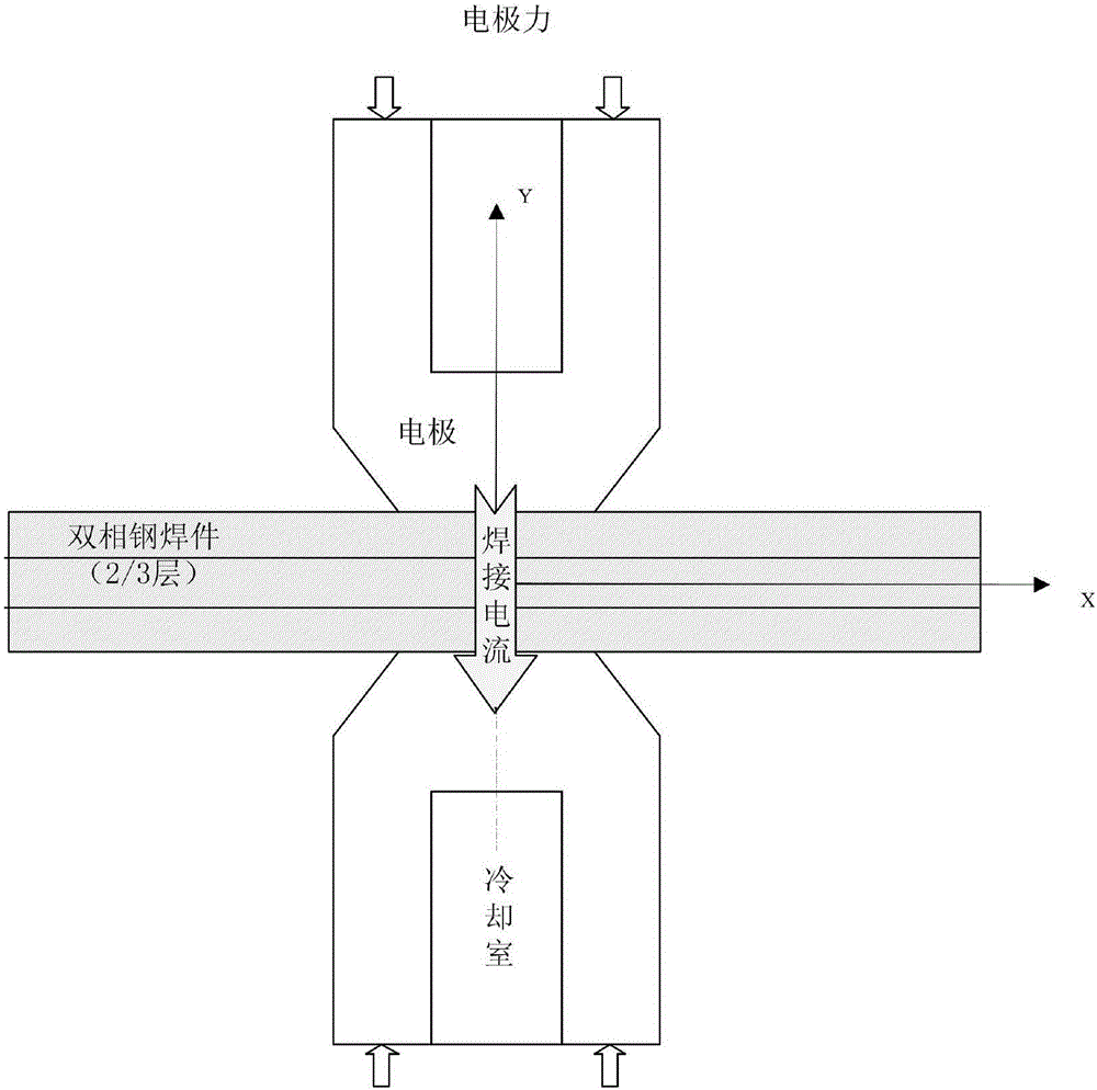
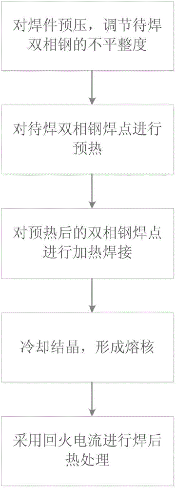
[0020] First of all, in order to avoid the adverse effects of other components on the surface on the welding quality, before welding the dual-phase steel to be welded, the surface is cleaned with acetone to ensure the cleanliness of the part to be welded. A schematic diagram of resistance spot welding and a process flow chart for improving the quality of dual-phase steel solder joints provided by the present invention are specifically as follows figure 1 , 2 As shown, it includes the following steps:

[0021] (a) Initially pressurize the dual-phase steel to be welded, and the pressurization time is 100-500ms, so that the two dual-phase steel plates are closely bonded, re...


PUM


Abstract

The invention discloses a resistance spot welding technology for improving quality of welding spots of dual-phase steel. The resistance spot welding technology comprises the steps that firstly, the flatness of the to-be-welded dual-phase steel is adjusted to be 1 mm / m or below through pressurization; then, a spot welding machine is connected with a current to preheat the to-be-welded dual-phase steel; after preheating, the welding current is adjusted, and the to-be-welded dual-phase steel is subjected to heating welding; and the welding current is cut off, spot-welded joints quickly cool and form molten cores, and after the molten cores cool to the martensitic structure transformation temperature or below, a temper current is connected, and postwelding temper heat treatment is carried out. According to the resistance spot welding technology for the dual-phase steel provided by the invention, before welding, the flatness of the to-be-welded dual-phase steel is adjusted, spot welding is carried out through the manner of preheating-heating-cooling crystallization-tempering, and the problems that liquid metal in the molten state splashes and affects the welding quality and possibly causes unintentional harm to human bodies during the welding process are avoided; and besides, the welding spots are relatively stable during the welding process, the welding deformation is reduced, a brittle structure is changed, the quality of the welding spots is improved, the welding spots are prevented from having shrinking holes and cracks, and the quality of a product is improved.

Description

technical field [0001] The invention relates to the field of automobile manufacturing, in particular to a resistance spot welding process for improving the quality of dual-phase steel solder joints. Background technique [0002] With the increasingly fierce competition in the automobile industry, automobile lightweight, energy saving and environmental protection have become important issues in the development of automobile design and manufacturing. Due to the characteristics of high strength and good processing performance, dual-phase steel not only shows obvious advantages in automobile lightweight, but also It has the characteristics of high weight reduction potential, high crash resistance, and high fatigue strength, which greatly improves the safety, reliability and comfort of automobiles. Therefore, the research and development and utilization of dual-phase steel materials are gradually emerging in the global automobile industry. However, the existing dual-phase steel i...

Claims


Application Information

Patent Timeline
Patent Type & Authority Applications(China)
IPC IPC(8): B23K11/11B23K11/34B23K103/04
CPCB23K11/11B23K11/34B23K2101/006B23K2103/04
Inventor 雷贞贞孟杰刘霜
Owner CHONGQING UNIVERSITY OF SCIENCE AND TECHNOLOGY
Learn More