
Conductive slip ring integrating circular inductive synchronizer and preparation method thereof

A technology of circular induction synchronizer and conductive slip ring, which can be applied to instruments, electric devices, electromagnetic means, etc., can solve the problems of twisted wires and increase of system volume, etc.

Inactive Publication Date: 2017-01-25
JIUJIANG JINGDA MEASUREMENT TECH
View PDF7 Cites 0 Cited by
  • Summary
  • Abstract
  • Description
  • Claims
  • Application Information

AI Technical Summary

Problems solved by technology

[0005] The first object of the present invention is to provide a circular induction synchronizer integrated with a conductive slip ring, which not only solves the problem of twisting of the rotor lead-out wires during operation, but also does not increase the system volume or introduce electromagnetic interference , which brings great convenience to the application of circular induction synchronizer

Method used


Image

  • Conductive slip ring integrating circular inductive synchronizer and preparation method thereof
  • Conductive slip ring integrating circular inductive synchronizer and preparation method thereof
  • Conductive slip ring integrating circular inductive synchronizer and preparation method thereof

Examples


Embodiment Construction

[0034] The present invention will be described in further detail below in conjunction with the embodiments and with reference to the accompanying drawings.

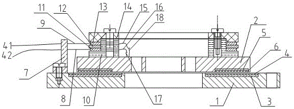
[0035]A circular induction synchronizer integrated with a conductive slip ring, including a stator base plate 1 installed on a fixed body and a rotor base plate 2 installed on a rotating shaft. Both the stator base plate 1 and the rotor base plate 2 are made of metal materials. A stator insulating layer 3 is fixed on the upper surface, a ring-shaped stator metal winding 4 is fixed on the stator insulating layer 3, a rotor insulating layer 5 corresponding to the position of the stator insulating layer is fixed on the lower surface of the rotor substrate 2, and a rotor insulating layer 5 is fixed on the rotor insulating layer. The ring-shaped rotor metal winding 6 is fixed on the 5, the stator metal winding 4 is placed opposite to the rotor metal winding 6, the stator metal winding 4 and the rotor metal winding 6 are both pe...


PUM


Abstract

The invention discloses a conductive slip ring integrating circular inductive synchronizer and a preparation method thereof. A base is fixed to a rotor base plate, a lower ring, an insulting sheet, an upper ring and a pressure plate sleeve the base, each of the upper and lower rings is provided with a V-shaped annular groove, and connection lines are led out from the upper and lower rings by means of welding and connected with rotor excitation input lines. A brush wire seat is fixed to a stator base plate, tail ends of upper and lower brush wires penetrate wire through holes of the brush wire seat to be inserted into the V-shaped annular grooves of the upper and lower rings, and connection lines are led out from the upper and lower brush wires by means of welding to serve as input signal lines. Since the input signal lines are finally connected with rotor excitation input ends, excitation signals can be applied to the input signal lines to drive a rotor to operate. The problem of twisting of rotor outgoing lines is solved during operation while increase of system volume and electromagnetic interference are avoided, and great convenience is brought to application of circular inductive synchronizers.

Description

technical field [0001] The invention relates to an angle sensor, in particular to a circular induction synchronizer integrated with a conductive slip ring and a preparation method. Background technique [0002] The circular induction synchronizer is an electromagnetic induction angle sensor, which has a series of advantages such as resistance to harsh environments, high measurement accuracy, long life, low cost, convenient installation, fast operation speed, stability and reliability, etc. It is often used in turntables, gyro platforms, Artillery control, navigation guidance, radar antenna, theodolite and other equipment. The circular induction synchronizer is divided into two parts, the stator and the rotor. Usually the stator is installed on the fixed body, and the rotor is installed on the rotating shaft. If the excitation signal is applied to the rotor, the stator will induce two-phase sine and cosine signals. During the working process, the rotating shaft drives the ro...

Claims


Application Information

Patent Timeline
IPC IPC(8): G01B7/30
CPCG01B7/30
Inventor 娄敏周萍王智勇周小全
Owner JIUJIANG JINGDA MEASUREMENT TECH
Learn More