Detecting state of parking brake member

A braking component and parking technology, applied in the direction of brakes, brake types, braking safety systems, etc., can solve the problems of reducing the reliability of parking braking components, increasing weight and volume, etc.

Pending Publication Date: 2020-12-04
SAFRAN LANDING SYSTEMS
View PDF0 Cites 0 Cited by
  • Summary
  • Abstract
  • Description
  • Claims
  • Application Information

AI Technical Summary

Problems solved by technology

[0014] The use of such a magnetic sensor presents undeniable advantages, but it also presents a certain cost, a...

Method used


Image

  • Detecting state of parking brake member
  • Detecting state of parking brake member
  • Detecting state of parking brake member

Examples


Embodiment Construction

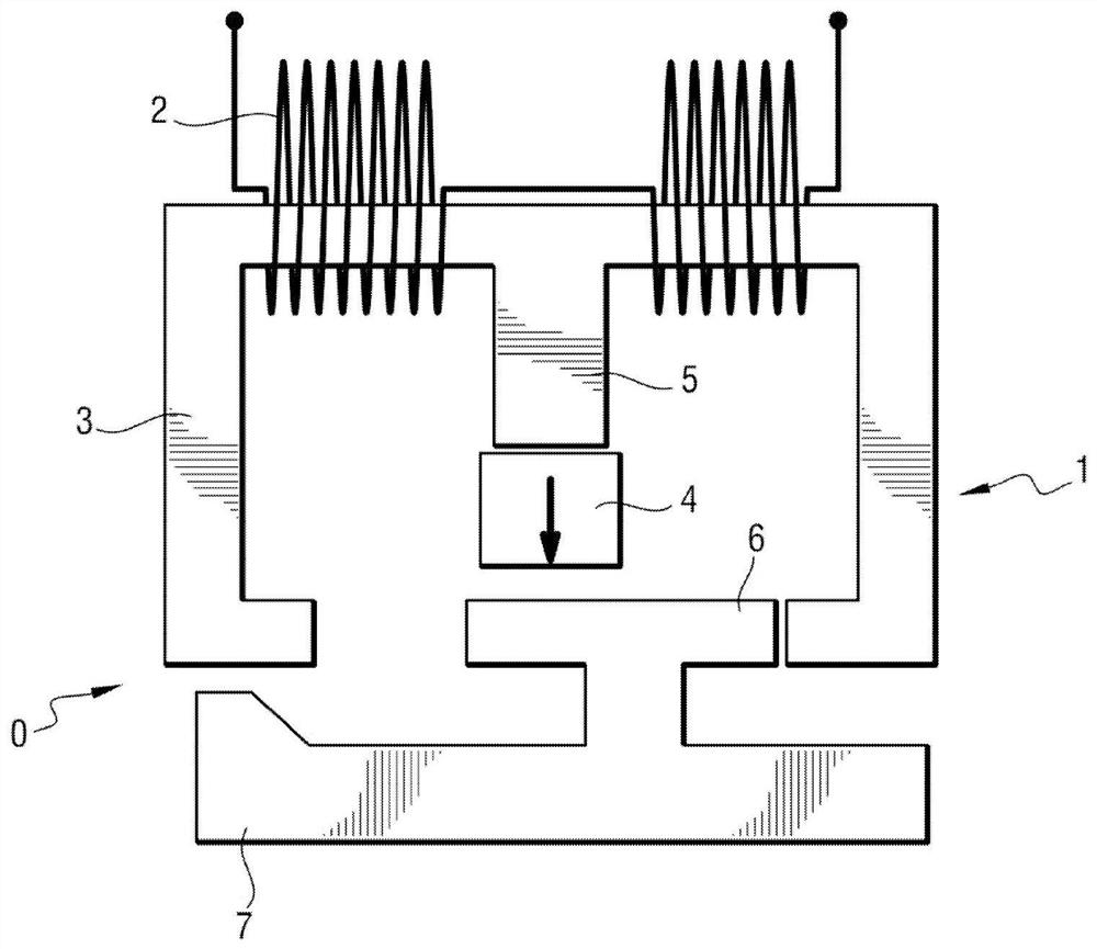
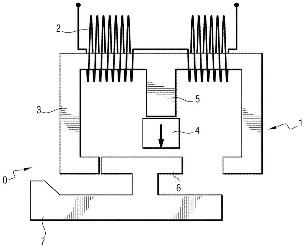
[0042] refer to figure 1 and 2 , in a first embodiment, an electromechanical brake actuator of a brake of an aircraft wheel comprising an electric motor and a parking brake member 0 comprising a bistable linear electromagnet.

[0043] The bistable linear electromagnet 1 comprises a coil 2 , an E-shaped ferromagnetic ring 3 , a permanent magnet 4 fastened to one end of a central branch 5 of this E-shape, and a shuttle 6 movable and connected to a rod 7 . The lever 7 cooperates with a dog connected to the output shaft of the electric motor of the electromechanical brake actuator.

[0044] Rod 7 is in the retracted position (e.g. figure 1 , where the parking brake member 0 is in the unlocked state and where the output shaft of the motor is released) versus the extended position (as in figure 2 , where the parking brake member 0 is blocked and where the output shaft of the motor is blocked) slides between.

[0045]The rod 7 is driven by a shuttle 6 mounted to slide in the rin...


PUM


Abstract

The invention discloses a detection method for detecting a blocked or unlocked state of a parking brake member comprising a bistable linear electromagnet (1). The parking brake member being connectedboth to a power supply assembly (14) arranged to generate a control voltage (Uc) and to a current sensor (15) arranged to measure a control current (Ic), the control voltage (Uc) being greater than the control current (Ic). The detection method comprises the steps: controlling the power supply assembly (14) to generate a test voltage (Utest) across the terminals of the coil and thus a test current(Itest) flowing in the coil, the test voltage having an amplitude less than a predetermined voltage threshold such that a test magnetic field generated by the test current does not shuttle; acquiringa measurement of the test current as generated by the current sensor (15); and analyzing the measurement of the test current and detecting a blocked or unlocked state of the parking brake member based on this analysis.

Description

technical field [0001] The invention relates to the field of bistable parking brake members. Background technique [0002] Modern aircraft, such as airplanes or helicopters, routinely include braking systems for braking the so-called "brake" wheels of the aircraft. The braking system comprises a plurality of brakes, each for braking one of the brake wheels of the aircraft. Each brake includes one or more friction members (eg, a carbon disc stack) and one or more brake actuators. The brake actuators are generally electromechanical actuators (then the system is called an "electric" brake system) or hydraulic actuators (then the system is called a "hydraulic" brake system). [0003] In an electric brake system, each electromechanical brake actuator consists of an electric motor and a screw-nut assembly, one of the components of which is driven in rotation by the motor and the other of which is constrained to slide without rotation so that the A compressive force is selective...

Claims


Application Information

Patent Timeline
IPC IPC(8): B64F5/60B60T17/22B64C25/42
CPCB64F5/60B60T17/22B64C25/42B60T13/741F16D2121/20B64C25/44F16D63/002F16D2066/003
Inventor B·戈耶兹G·杜兰德E·克莱拉丁
Owner SAFRAN LANDING SYSTEMS
Why Eureka
Try Eureka