Double ended led tube light

An LED tube lamp, double-ended technology, which is applied in the direction of lampshade, cooling/heating device of lighting device, lighting and heating equipment, etc. low effect

Active Publication Date: 2018-02-16
SHANGHAI RUN CHAN OPTICAL TECH
View PDF7 Cites 0 Cited by
  • Summary
  • Abstract
  • Description
  • Claims
  • Application Information

AI Technical Summary

Problems solved by technology

[0006] (1) The lamp tube adopts a half-aluminum and half-plastic structure, and has a built-in AC-DC non-isolated LED drive power supply, and the lamp tube is connected to the output end of the electronic rectifier that drives the fluorescent lamp, without changing the control device and circuit connection of the original lamp The lamp cannot be effectively grounded when
For this reason, there are potential safety hazards and risks in the use of such lamps.
[0007] (2) Since the existing LED tube lights adopt AC-DC non-isolated LED drive mode, the circuit is more complicated and the cost is higher
This will short-circuit the rectifier filament circuit in the case of some electronic rectifiers for fluorescent lamps that deliver filament current to the driven fluorescent lamp, resulting in incompatibility
[0009] (4) Since the existing lamp tube has a built-in AC-DC non-isolated LED driver, the built-in drive power supply needs to be set in the milky white opaque plugs of about 40mm at both ends of the tube lamp, resulting in a gap of about 40mm at both ends of the lamp tube. dark area
At the same time, due to the heat emitted by the power supply, the nearby LEDs are heated and the temperature rises, which affects the service life of the LED tube lamp.
[0010] For this reason, there are many unsatisfactory problems in terms of service life, safety and cost, etc., when LED tube lamps with existing structures directly replace traditional fluorescent tubes.

Method used


Image

  • Double ended led tube light
  • Double ended led tube light
  • Double ended led tube light

Examples


Embodiment Construction

[0039] The specific implementation manners of the present invention will be described in detail below in conjunction with the accompanying drawings of the embodiments.

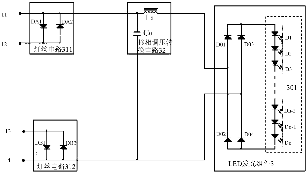
[0040] see figure 1 , the double-ended LED tube lamp of the present invention is an LED tube lamp replacing a fluorescent tube, which includes:

[0041] Lamp cover 5 is a circular tubular two-color PC cover. Its front side is a light-emitting surface 51, and its back side is an opaque surface 52. Viewed from the cross-section, the arc of the light-emitting surface 51 is 220°, and the arc of the opaque surface 52 is 140°; its external dimensions are exactly the same as the replaced fluorescent tube (diameter, length, etc.), and can directly replace the fluorescent lamp of the same specification Tube.

[0042] The heat-dissipating aluminum profile 4 is placed in the lamp cover 5 with a groove 41 in the middle, and two symmetrical slots 42 are arranged on both sides of the groove 41 .

[0043]The aluminum subs...


PUM


Abstract

The invention is a double-ended LED tube lamp, which is used to replace fluorescent tubes and solves the problems of unsafe use and short life of the existing replacement technology. It includes: a tube cover, which is a round tubular two-color PC cover; Placed in the lamp cover; the aluminum base plate is clamped in the heat-dissipating aluminum profile; the LED light-emitting component is composed of an LED light-emitting module and a bridge rectifier circuit, and is fixed on the aluminum base plate; a pair of plugs connect the two ends of the lamp cover The end is closed, and a pair of electrode pins connected with the electronic rectifier of the fluorescent lamp are provided on the outside of each plug to form a double-ended LED tube lamp. The plug is equipped with a PCB board installed with a phase-shifting and voltage-regulating conversion circuit and a filament circuit. It is electrically connected with the electrode pin, and the output end is connected with the LED light-emitting component. LED tube lights have the same dimensions as the fluorescent tubes they replace. The lamp cover of this tube lamp is an all-plastic structural part, which is safe to use. The LED tube lamp is fully compatible with the electronic rectifier of the fluorescent lamp, and can directly replace the fluorescent lamp.

Description

technical field [0001] The invention relates to an LED tube lamp, in particular to a double-ended LED tube lamp. Background technique [0002] Fluorescent lamps are widely used traditional lighting fixtures. Existing fluorescent lamps are composed of high-frequency electronic rectifiers, fluorescent tubes, lamp holders, wires, and lamp structural parts. Existing LED lamps are composed of LED lamp tubes, constant current drivers, lamp holders, wires, lamp structural parts and the like. Compared with the two, LED lights have significant energy-saving advantages. For this reason, replacing traditional fluorescent lamps with LED lamps is inevitable for the development of lighting science and technology. [0003] The traditional fluorescent tube is a gas discharge lamp, which can be driven by a high-frequency AC power supply, while the LED tube lamp is a single-phase conductive diode load, which needs to be driven by a DC constant current power supply, so the driving method and...

Claims


Application Information

Patent Timeline
Patent Type & Authority Patents(China)
IPC IPC(8): F21S2/00F21V3/06F21V29/00F21V17/16F21V17/12F21V23/00F21Y115/10
Inventor 曾浩然邵继平
Owner SHANGHAI RUN CHAN OPTICAL TECH
Why Eureka
Try Eureka