
Mars machine-machine separating orbit design method

A design method and orbit technology, applied to aircraft, space navigation equipment, space navigation equipment, etc., can solve the problems of increasing the risk of the orbiter, the distance from the surface of Mars, the distance from the ground fire, etc., and achieve the effect of saving fuel consumption

Active Publication Date: 2017-01-18
SHANGHAI AEROSPACE CONTROL TECH INST
View PDF4 Cites 14 Cited by
  • Summary
  • Abstract
  • Description
  • Claims
  • Application Information

AI Technical Summary

Problems solved by technology

The Viking probe uses the lander to descend into the landing orbit at the apogee. It is more convenient to design the landing orbit at this point and the landing orbit is uniquely determined, but it is far away from the surface of Mars. Due to the influence of the orbit measurement on the ground, the landing accuracy of the lander is relatively low. Difference,
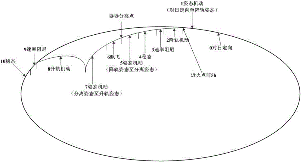
[0003] like figure 2 As shown, there are many attitude maneuvers and orbital maneuvers performed during the separation stage of the vehicle. Excessive running time in the collision orbit will increase the risk of the orbiter and increase fuel consumption. During the separation period, the ground cannot be measured and remotely controlled in real time, so the orbiter’s de-orbit time should not be too long. After separation, choose an opportunity to ascend the orbit

Method used


Image

  • Mars machine-machine separating orbit design method
  • Mars machine-machine separating orbit design method
  • Mars machine-machine separating orbit design method

Examples


Embodiment Construction

[0034] The present invention will be further elaborated below by describing a preferred specific embodiment in detail in conjunction with the accompanying drawings.

[0035] A method for designing the separation orbit of the Mars vehicle, which is used in the separation process of the orbiter and the lander. In order to improve the landing accuracy of the lander, the de-orbit maneuver is selected after the far-fire point As an example), the Mars vehicle separation orbit design method includes the following steps:

[0036] S1. In the near-focus coordinate system, according to the position and speed of the probe when it enters the Martian atmosphere, establish the Mars vehicle separation orbit design equation with the eccentricity of the landing orbit as an independent variable.

[0037] In the step S1, the X-axis and Y-axis of the near-focus coordinate system are in the orbital plane of the detector, the origin is at the center of Mars, the X-axis of the near-focus coordinate s...


PUM


Abstract

The invention discloses a Mars machine-machine separating orbit design method. The method comprises the following steps: S1. under a near focus coordinate system, establishing a Mars machine-machine separating orbit design equation taking landing orbit eccentricity as independent variable; and S2. by taking the minimum speed increment during orbit transfer of a landing machine as a target function, solving the Mars machine-machine separating orbit design equation by adopting a preset solving algorithm to obtain the landing orbit of the landing machine, thus completing the Mars machine-machine separating orbit design. According to the method, the minimum speed increment during orbit transfer as the target (landing through the shortest starting time of an engine), the constraint condition of an entrance angle when the landing machine enters Mars atmosphere can be met, and the method is simple and feasible and provides support for deep space detection machine-machine separation.

Description

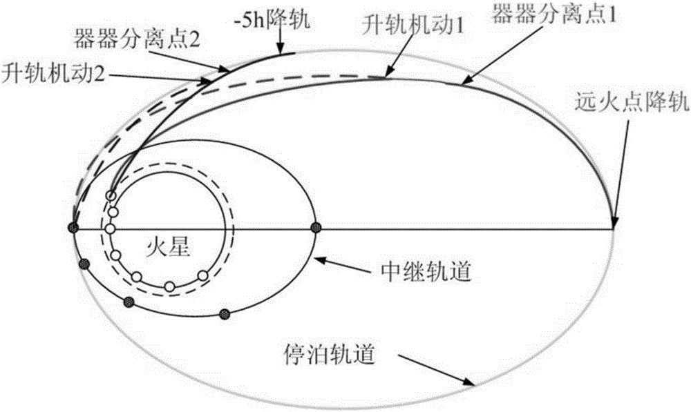
technical field [0001] The invention relates to a Mars exploration orbit control technology, in particular to a method for designing a Mars vehicle separation orbit. Background technique [0002] my country will launch a Mars probe in 2020 to achieve orbiting, landing, and inspection tasks. The orbiter carries the lander to achieve capture and braking. After orbit adjustment, it enters the parking orbit. 5 hours before the near fire point, the orbiter descends orbit and maneuvers into the collision. In the fire track, the orbiter and the lander are separated from the actuators on the fire track, and then the orbiter chooses an opportunity to ascend into the ring fire track, such as figure 1 shown. The landing trajectory is usually designed with the constraint of the entry angle of the lander into the Martian atmosphere. The Viking probe uses the lander to descend into the landing orbit at the apogee point. It is more convenient to design the landing orbit at this point and ...

Claims


Application Information

Patent Timeline
Patent Type & Authority Applications(China)
IPC IPC(8): B64G1/24
CPCB64G1/242
Inventor 刘付成冯建军王卫华周誌元聂钦博祖立业朱庆华周杰
Owner SHANGHAI AEROSPACE CONTROL TECH INST
Learn More