High-temperature wear-resistant alloy guide roll of finishing mill and preparation method thereof

A technology of high-temperature wear-resistant alloy and finishing mill, which is applied in the direction of rolls, metal rolling, metal rolling, etc., can solve the problems of low service life, poor high-temperature wear resistance, short service life of guide rolls, etc., and achieve high wear resistance performance, improve high temperature resistance, and protect the service life

Active Publication Date: 2018-04-10
HEFEI ORIENT METALLURGICAL EQUIP
View PDF5 Cites 0 Cited by
  • Summary
  • Abstract
  • Description
  • Claims
  • Application Information

AI Technical Summary

Problems solved by technology

[0002] The guide roller is a part that causes the plastic deformation of the rolled steel during the rolling process of the section steel. It mainly bears the dynamic and static loads and wear during rolling. impact, the service life of the guide roller is short, the consumption is large, and the replacement is frequent, and it has become one of the bottlenecks restricting steel production
[0003] The early guide roller materials were alloy carbon steel and cast iron, which had poor wear resistance and low service life. Later, WC cemented carbide was used. Although the wear resistance was effectively improved, it still had high brittleness and resistance to heat and chill. Poor performance, "steel sticking" phenomenon will occur during use, resulting in the failure of smooth rolling of red steel, which will affect the surface quality of the product. Nickel-based guide materials have good thermal shock resistance and high temperature oxidation resistance, but they are expensive and economical. Poor, at present, most of the guide rolls of rolling mills are made of austenitic heat-resistant steel, which has good high temperature stability and toughness, but its high temperature wear resistance is poor, resulting in serious product wear and low service life
[0004] The manufacturing process of traditional guide rollers using smelting and injection molding is relatively complicated, and it cannot be repaired after damage

Method used


Image

  • High-temperature wear-resistant alloy guide roll of finishing mill and preparation method thereof

Examples


Embodiment 1

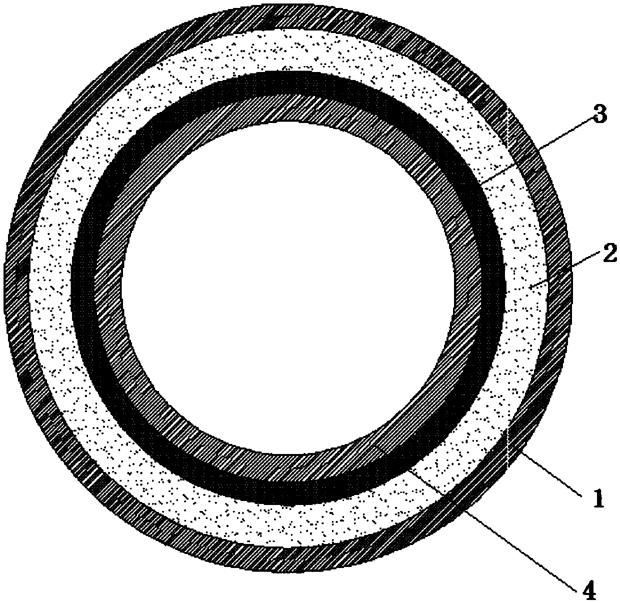
[0023] A high-temperature wear-resistant alloy guide roll for a finishing mill, comprising a first metal layer 1, a ceramic layer 2, an elastic layer 3 and a second metal layer 4;

[0024] The inner surface of the first metal layer 1 is bonded with a ceramic layer 2;

[0025] The inner surface of the ceramic layer 2 is fitted with a second metal layer 4;

[0026] Wherein, the second metal layer 4 is in clearance fit with the ceramic layer 2;

[0027] Wherein, an elastic layer 3 is arranged between the ceramic layer 2 and the second metal layer 4 .

[0028] Wherein, the first metal layer 1 contains (Cr, Fe) 7 C 3 Carbide; the second metal layer 4 is a stainless steel tube.

[0029] Wherein, the elastic layer 3 is silicone rubber; the elastic layer 3 is in interference fit with the gap formed by the ceramic layer 2 and the second metal layer 4 .

[0030] A method for preparing a high-temperature wear-resistant alloy guide roll of a finishing mill, comprising the following s...

Embodiment 2

[0038] A high-temperature wear-resistant alloy guide roll for a finishing mill, comprising a first metal layer 1, a ceramic layer 2, an elastic layer 3 and a second metal layer 4;

[0039] The inner surface of the first metal layer 1 is bonded with a ceramic layer 2;

[0040] The inner surface of the ceramic layer 2 is fitted with a second metal layer 4;

[0041] Wherein, the second metal layer 4 is in clearance fit with the ceramic layer 2;

[0042] Wherein, an elastic layer 3 is arranged between the ceramic layer 2 and the second metal layer 4 .

[0043] Wherein, the first metal layer 1 contains (Cr, Fe) 7 C 3 Carbide; the second metal layer 4 is a stainless steel tube.

[0044] Wherein, the elastic layer 3 is silicone rubber; the elastic layer 3 is in interference fit with the gap formed by the ceramic layer 2 and the second metal layer 4 .

[0045] A method for preparing a high-temperature wear-resistant alloy guide roll of a finishing mill, comprising the following s...

Embodiment 3

[0053]A high-temperature wear-resistant alloy guide roll for a finishing mill, comprising a first metal layer 1, a ceramic layer 2, an elastic layer 3 and a second metal layer 4;

[0054] The inner surface of the first metal layer 1 is bonded with a ceramic layer 2;

[0055] The inner surface of the ceramic layer 2 is fitted with a second metal layer 4;

[0056] Wherein, the second metal layer 4 is in clearance fit with the ceramic layer 2;

[0057] Wherein, an elastic layer 3 is arranged between the ceramic layer 2 and the second metal layer 4 .

[0058] Wherein, the first metal layer 1 contains (Cr, Fe) 7 C 3 Carbide; the second metal layer 4 is a stainless steel tube.

[0059] Wherein, the elastic layer 3 is silicone rubber; the elastic layer 3 is in interference fit with the gap formed by the ceramic layer 2 and the second metal layer 4 .

[0060] A method for preparing a high-temperature wear-resistant alloy guide roll of a finishing mill, comprising the following st...


PUM


Abstract

The invention discloses a high-temperature wear-resistant alloy guide roll of a finishing mill and a preparation method thereof. It includes a first metal layer, a ceramic layer, an elastic layer and a second metal layer; the inner surface of the first metal layer is bonded with a ceramic layer; the inner surface of the ceramic layer is matched with a second metal layer; the second The metal layer is in clearance fit with the ceramic layer; an elastic layer is fit between the ceramic layer and the second metal layer. The invention effectively improves the high temperature resistance performance of the alloy guide roller by adopting (Cr, Fe)7C3 carbide, ceramics and stainless steel to synthesize the guide roller structure layer, so that the heat can be cut off in the ceramic layer, and the use of the bearing can be effectively protected. Long service life; when the outer surface of the guide roller is damaged, remove the alloy tube of the first metal layer and replace it with a new first metal layer, which improves the continuous use of the guide roller under high wear resistance process.

Description

technical field [0001] The invention belongs to the technical field of mechanical guide rolls, in particular to a high-temperature wear-resistant alloy guide roll of a finishing mill and a preparation method thereof. Background technique [0002] The guide roller is a part that causes the plastic deformation of the rolled steel during the rolling process of the section steel. It mainly bears the dynamic and static loads and wear during rolling. The impact makes the service life of the guide roller short, the consumption is large, and the replacement is frequent, and it has become one of the bottlenecks restricting the production of steel products. [0003] The early guide roller materials were alloy carbon steel and cast iron, which had poor wear resistance and low service life. Later, WC cemented carbide was used. Although the wear resistance was effectively improved, it still had high brittleness and resistance to heat and chill. Poor performance, "steel sticking" phenome...

Claims


Application Information

Patent Timeline
Patent Type & Authority Patents(China)
IPC IPC(8): B21B27/02C22C37/10C22C37/06
CPCB21B27/02C22C37/06C22C37/10
Inventor 赵家柱张有德常焰平吴涛郁应海史宣菊
Owner HEFEI ORIENT METALLURGICAL EQUIP
Why Eureka
Try Eureka