
Eureka
For R&D, Eureka makes reading and utilizing patents & technical documents easy.
Eureka AIR
Designed for self-driven R&D workflows. Generate viable solutions, solve complex R&D challenges, empower your innovation with AI.

Eureka Materials
Designed for material experts only. Revolutionize your material R&D, from search, analyze, to developing new materials.

TechResearch
Generate reliable direction feasibility study reports for your R&D in just a few steps.

TechSeek
Discover and master advanced knowledge NOW. Basics, ideas, possibilities, all at once.

TechMind
As an expert in R&D Theories, TechMind can generates customized viable solutions instantly.

TechRisk
Analyze your overall solution with one click, know your potential R&D risks in advance.

TechMonitor
Get weekly tech updates, stay abreast of the latest tech innovations and key insights.
Turning blade variable in chamfered edge width and angle
A chamfering and turning technology, which is applied to cutting blades, turning equipment, manufacturing tools, etc., can solve the problems of processing efficiency, safety, poor surface quality of workpieces, and easy entanglement of chips on tools, workpieces or machine tools. Influence, reduce radial force, reduce the effect of tool stress concentration
- Summary
- Abstract
- Description
- Claims
- Application Information
AI Technical Summary
Problems solved by technology
Method used
Image

Examples
specific Embodiment approach 1
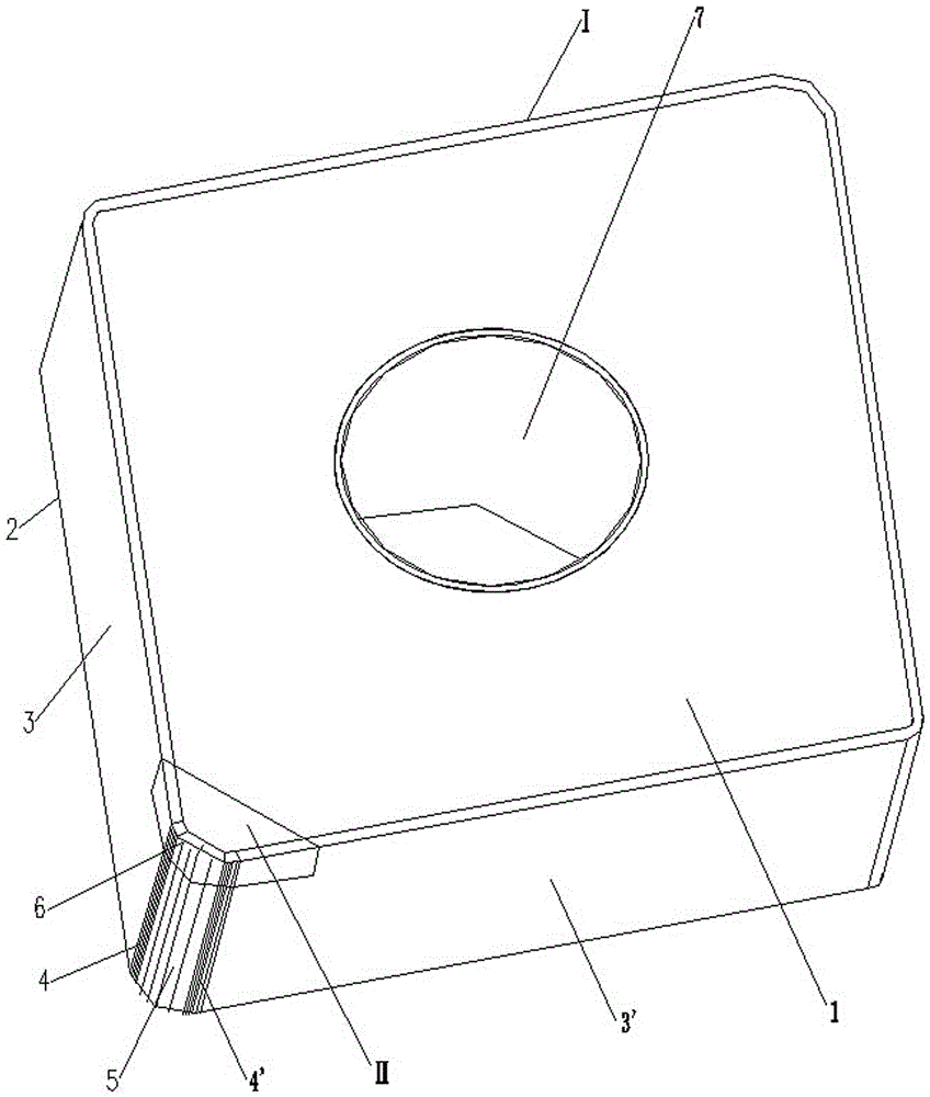
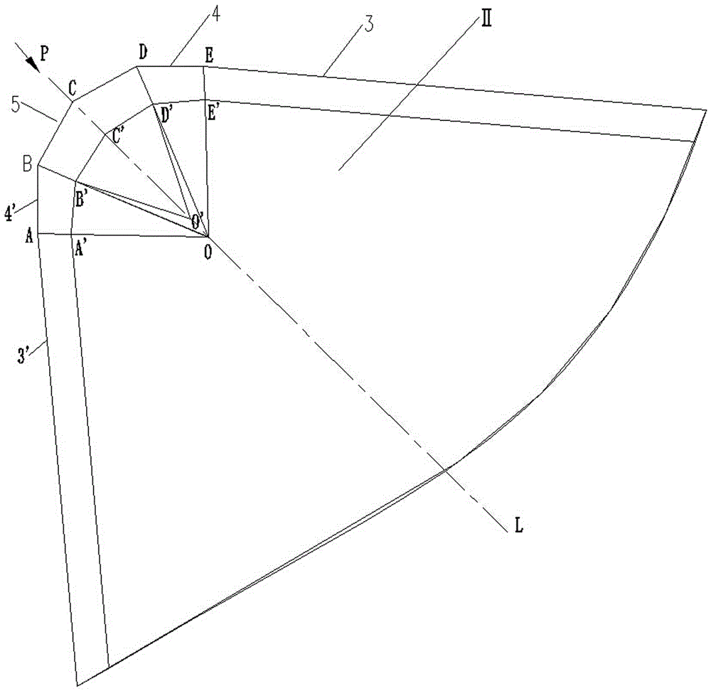
[0022] Specific implementation mode one: as Figure 1~Figure 6 As shown, a turning insert with variable chamfer width and angle, the turning insert is composed of a cutter body I and a tip insert II, and the middle part of the cutter body I is provided with a tool holder mounting hole 7 (knife The rod mounting hole 7 is chamfered to facilitate installation), the horizontal section of the cutter body I is polygonal, and any corner of the upper surface of the cutter body I is provided with an embedding groove that matches the blade tip insert II, so The blade tip insert II is tightly embedded in the embedding groove of the cutter body I, and the side surfaces of the turning insert include side one 3, side two 3', smoothing surface one 4, smoothing surface two 4' and the curved surface 5 of the knife tip. The cutting edge of the cutting edge insert II is provided with a cutting edge cutting section, and the cutting edge cutting section is processed with a variable chamfer surface...
specific Embodiment approach 2
[0032] Specific implementation mode two: as figure 1 and figure 2 As shown, the turning insert with variable chamfer width and angle described in the first embodiment, the first smoothing surface 4 or the second smoothing surface 4' is parallel to the feeding direction of the turning insert.
specific Embodiment approach 3
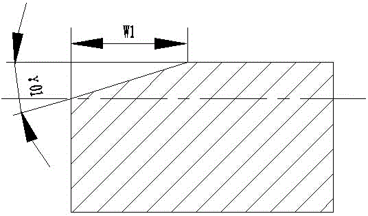
[0033] Specific implementation mode three: as figure 1 and figure 2 As shown, the turning insert with variable chamfer width and angle described in the first specific embodiment, the width of the variable chamfer surface ranges from 0.1 to 0.3mm, and the chamfer angle of the variable chamfer surface takes The value range is -5°~-25°. The effect is: If the chamfer width and chamfer angle are too large, the cutting force generated during the cutting process will be too large, and the vibration generated during machining will also increase, which will affect the quality of the processed surface. If the value is too small, the effect of chamfering is not obvious.
PUM
 Abstract
Description
Claims
Application Information
 - R&D Engineer
- R&D Manager
- IP Professional
- Industry Leading Data Capabilities
- Powerful AI technology
- Patent DNA Extraction
Browse by: Latest US Patents, China's latest patents, Technical Efficacy Thesaurus, Application Domain, Technology Topic, Popular Technical Reports.
© 2024 PatSnap. All rights reserved.Legal|Privacy policy|Modern Slavery Act Transparency Statement|Sitemap|About US| Contact US: help@patsnap.com