A centrifugal microfluidic chip and a method for continuously synthesizing janus particles

A microfluidic chip and centrifugal technology, applied in the field of microfluidics, to achieve the effect of improving the synthesis yield

Active Publication Date: 2018-10-23
NORTHEASTERN UNIV LIAONING
View PDF6 Cites 0 Cited by
  • Summary
  • Abstract
  • Description
  • Claims
  • Application Information

AI Technical Summary

Problems solved by technology

[0006] Aiming at the problems existing in the production rate of Janus particles synthesized by existing microfluidic methods, the present invention provides a centrifugal microfluidic chip and a method for continuously synthesizing Janus particles

Method used


Image

  • A centrifugal microfluidic chip and a method for continuously synthesizing janus particles
  • A centrifugal microfluidic chip and a method for continuously synthesizing janus particles
  • A centrifugal microfluidic chip and a method for continuously synthesizing janus particles

Examples


Embodiment 1

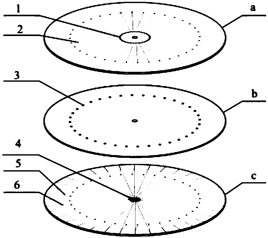
[0056] The centrifugal microfluidic chip of the present invention, such as figure 1 As shown, it is composed of an upper substrate a, an intermediate substrate b and a lower substrate c; the upper substrate, the intermediate substrate and the lower substrate are concentric circles and are equal in size;

[0057] For the upper substrate, an upper central circular hole is arranged at the center of the upper substrate; an annular liquid pool 1 is arranged on the upper substrate, and the annular liquid pool 1 is concentric with the upper substrate a, and the annular liquid pool 1 is concentric with the upper substrate a. The pool 1 penetrates the upper substrate a, and the outer side of the annular liquid pool 1 is provided with several upper dispersed circular channels, and several upper dispersed circular channels are evenly distributed on the upper substrate along the circumferential direction. The annular liquid pools are connected through a first-level straight channel 2, and...

Embodiment 2

[0087] The structure and material of the centrifugal microfluidic chip used in this example are the same as in Example 1, but the size is different:

[0088] In this implementation, the diameter of the annular liquid pool is 14mm, and the diameter of the upper substrate is 70mm, then S:D=14:70; and the difference between the inner diameter and outer diameter of the upper annular liquid pool is 1mm;

[0089] In this implementation, the upper substrate is provided with 36 upper dispersed circular holes, and the diameter of the upper dispersed circular hole is 0.9 mm; the center distance between the upper dispersed circular channel and the upper substrate is 28.45 mm;

[0090] In this implementation, the width of the first-level straight channel=the width of the second-level straight channel=the width of the third-level straight channel, both of which are 200 μm;

[0091] In this implementation, the distance between the connecting point of the secondary straight channel and the t...


PUM


Abstract

The invention discloses a centrifugal micro-fluidic chip and a method for continuously synthesizing Janus particles. The chip consists of an upper-layer substrate, a middle-layer substrate and a lower-layer substrate, wherein an upper-layer central round hole, a circular solution tank, multiple upper-layer round dispersion channels and multiple first-level straight channels which communicate are formed in the upper-layer substrate; a middle-layer central round hole is formed in the middle-layer substrate; a central solution tank, a lower-layer round dispersion channel, multiple second-level straight channels and multiple third-level straight channels are formed in the lower-layer substrate. The method comprises steps as follows: 1) the centrifugal micro-fluidic chip is fixed on a suction cup of a spin coater; 2) different test solutions are injected into the central solution tank and the circular solution tank, the spin coater is started for spin centrifugation, and bi-phase droplets are formed at channel outlets; 3) the bi-phase droplets are spun into the external circular solution tank to form the Janus particles. With the adoption of the method, continuous introduction of the test solutions is guaranteed and continuous synthesis of the bi-phase particles is realized; the synthesis rate of the Janus particles is increased due to the arrayed synthesis channels, drive solutions rotating at the high speed and continuous synthesis.

Description

technical field [0001] The invention belongs to the field of microfluidic technology, in particular to a centrifugal microfluidic chip and a method for continuously synthesizing Janus particles. Background technique [0002] Janus is a god with two faces in ancient Roman mythology. In 1991, De Gennes used Janus to visualize asymmetric particles for the first time in his Nobel acceptance speech. Because different properties can be exhibited on the same particle, this Janus particle with asymmetric double-sided structure shows better performance than particles with a single property in some application fields, such as emulsion stability, optics, biosensing , drug delivery, and electronics have potential applications. [0003] The synthesis method based on microfluidic technology has high mass and heat transfer efficiency, easy and accurate control of reaction conditions, fast mixing speed, and low reagent consumption. The use of microfluidic technology in the synthesis of Ja...

Claims


Application Information

Patent Timeline
Patent Type & Authority Patents(China)
IPC IPC(8): B01J19/00
CPCB01J19/0093
Inventor 徐章润宋丹孙小婷刘梅杨春光
Owner NORTHEASTERN UNIV LIAONING
Why Eureka
Try Eureka