
Low-field nuclear magnetic resonant antenna

A low-field nuclear magnetic resonance and nuclear magnetic resonance technology, which is applied in the direction of resonant antennas and mid-position feeds between antenna endpoints, can solve problems such as high prices, increased antenna equipment costs, and complex antenna structures.

Inactive Publication Date: 2017-01-04
BEIJING UNIV OF TECH
View PDF4 Cites 2 Cited by
  • Summary
  • Abstract
  • Description
  • Claims
  • Application Information

AI Technical Summary

Problems solved by technology

Today's antennas have good imaging effects, but these antennas are complex and expensive
For example, most of the MRI equipment in the hospital now uses gradient field coils and radio frequency coils. The construction principle and the sensitivity requirements of the radio frequency coils are very high, which leads to an increase in the cost of antenna equipment.

Method used


Image

  • Low-field nuclear magnetic resonant antenna
  • Low-field nuclear magnetic resonant antenna

Examples


Embodiment Construction

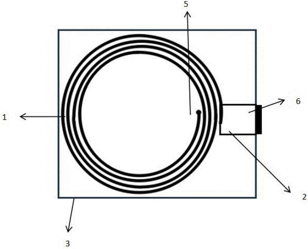
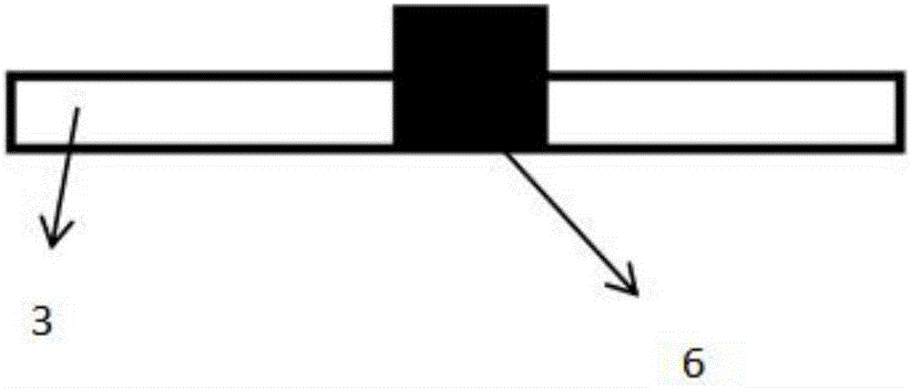
[0013] Such as figure 1 , 2 As shown, a kind of nuclear magnetic resonance antenna of the present invention can act on 5Mhz-10Mhz wave band imaging, comprises helical coil (1), resonant capacitor (2), substrate (3), ideal ground plane (4), via hole (5 ), SMA interface (6). The low-field nuclear magnetic resonance antenna has a helical coil (1), a resonant capacitor (2), a substrate (3), and an ideal ground plane (4) sequentially from top to bottom. The spiral coil (1) and the resonant capacitor are on the upper surface of the substrate (3), the ideal ground plane (4) is on the lower surface of the substrate (3), the middle is connected by a via (5), and the SMA interface (6) is on the edge of the substrate . The helical coil (1), resonant capacitor (2), and ideal ground plane (4) are all composed of copper patches. The upper surface is the helical coil (1) and resonant capacitor (2), and the lower surface is the ideal ground plane (4) . The entire antenna has a simple str...


PUM


Abstract

The invention relates to a low-field nuclear magnetic resonant antenna. The antenna is a nuclear magnetic resonant antenna acting in the range of 5-10 Mhz and comprises a spiral coil, a resonant capacitor, a substrate, an SMA interface and an ideal ground plane. The antenna generates a nanovolt voltage under excitation of a space electromagnetic wave, the curvature of a spiral coil patch is nonuniform, the patch has a certain width, a metal patch resonant capacitor of 1 millimeter is connected with the spiral coil patch to jointly form a resonant unit, the patch is placed on an FR4 material, and the ideal ground plane is a larger patch on a lower surface of the antenna substrate. The antenna can be used for receiving a weak signal generated after water molecules are stimulated, the antenna is small in size and is portable, the complexity of an antenna structure and the precision limitation of the antenna are reduced, so that the fabrication cost of the antenna is reduced, and the problem of poor mobility of nuclear magnetic resonant equipment is solved.

Description

technical field [0001] The invention relates to the fields of medical detection and detection of water resources, and can be applied to the detection of human lesion tissues, the detection of water resources in geological surveying, and the like. Background technique [0002] The antenna of the invention is used for receiving radio signals generated by water molecules in the electromagnetic wave environment generated by strong voltage. Today's antennas are good at imaging, but they are complex and expensive. For example, most of the current nuclear magnetic resonance equipment in hospitals uses gradient field coils and radio frequency coils. Their construction principles and requirements for the sensitivity of radio frequency coils are very high, resulting in an increase in the cost of antenna equipment. Therefore, the present invention focuses on reducing the complexity of the antenna structure and the limitation on the precision of the antenna, thereby reducing the manufa...

Claims


Application Information

Patent Timeline
Patent Type & Authority Applications(China)
IPC IPC(8): H01Q9/27
CPCH01Q9/27
Inventor 赛景波李智勇
Owner BEIJING UNIV OF TECH
Learn More