
Liquid discharge plasma emission spectroscopy device and metallic element determining method

A discharge plasma and emission spectroscopy technology, applied in the field of atomic emission spectroscopy analysis and testing in analytical chemistry, can solve the problems of high cost of dual-channel peristaltic pumps, large volume of samples to be tested, and inability to continuously inject samples, and achieve excellent discharge stability. , The effect of improving the photoexcitation efficiency and reducing the power

Inactive Publication Date: 2017-01-04
NORTHWEST NORMAL UNIVERSITY
View PDF5 Cites 11 Cited by
  • Summary
  • Abstract
  • Description
  • Claims
  • Application Information

AI Technical Summary

Problems solved by technology

However, the above two devices have the following disadvantages: 1) The volume of the sample to be tested is large (the test sample must first fill the reservoir), and continuous sampling cannot be performed; 2) The liquid level in the reservoir needs to be used to control the discharge. Stability and continuity, this process is more difficult; 3) The cost of using a dual-channel peristaltic pump is high and the process is complicated

Method used


Image

  • Liquid discharge plasma emission spectroscopy device and metallic element determining method
  • Liquid discharge plasma emission spectroscopy device and metallic element determining method
  • Liquid discharge plasma emission spectroscopy device and metallic element determining method

Examples


Embodiment 1

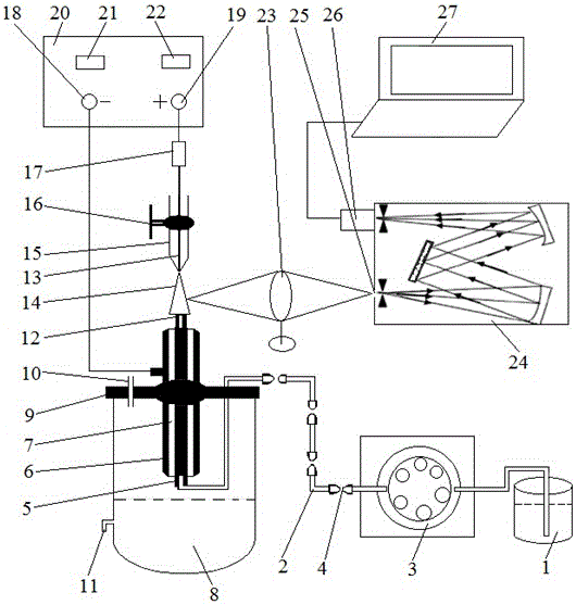
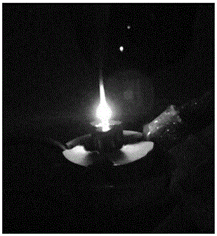
[0043] The position between the platinum electrode 13 and the capillary top part 12 is adjusted by the translation stage 16, so that the platinum electrode 13 and the capillary top part 12 are on the same axis, and the distance between the platinum electrode 13 and the capillary top part 12 is 2mm; The length is 3mm; HNO with pH=1 3 Put the solution into the sample pool 1, turn on the peristaltic pump 3, make the solution to be tested flow into the capillary 5 at a flow rate of 4.5 mL / min, and overflow from the top part 12 of the capillary to form a fountain-like liquid surface, adjust the translation platform 16 to make the fountain-like liquid The surface is just in contact with the lower end surface of the platinum electrode 13; the DC stabilized power supply 20 is turned on, at this time, the fountain-like liquid surface becomes the cathode of the liquid discharge, and the platinum electrode 13 becomes the anode, and a voltage of 650V and a current of 70mA are applied betwe...

Embodiment 2

[0052] The position between the platinum electrode 13 and the capillary top part 12 is adjusted by the translation stage 16, so that the platinum electrode 13 and the capillary top part 12 are coaxial, and the distance between the platinum electrode 13 and the capillary top part 12 is 1 mm; the capillary top part 12 The length of the test solution is 2mm; put the solution to be tested into the sample pool 1, turn on the peristaltic pump 3, make the solution to be tested flow into the capillary 5 at a flow rate of 1mL / min, and overflow from the top part 12 of the capillary to form a fountain-like liquid level, adjust the translation Platform 16 makes this fountain-like liquid surface just contact with the lower end platinum wire surface of conical platinum electrode 13; Apply a voltage of 640 V and a current of 95 mA between the electrodes, and the liquid overflowing from the top part of the capillary 12 will be vaporized and broken down to generate glow and form the excitation ...

Embodiment 3

[0054] The position between the platinum electrode 13 and the capillary top portion 12 is adjusted by the translation stage 16, so that the platinum electrode 13 and the capillary top portion 12 are coaxial, and the distance between the platinum electrode 13 and the capillary 12 is 3mm; the length of the capillary top portion 12 4mm; put the solution to be tested into the sample pool 1, turn on the peristaltic pump 3, make the solution to be tested flow into the capillary 5 at a flow rate of 6 mL / min, and overflow from the top part 12 of the capillary to form a fountain-like liquid level, adjust the translation stage 16 Make the fountain-like liquid surface just in contact with the lower end surface of the platinum electrode 13; turn on the DC stabilized power supply 20, at this time, the fountain-like liquid surface becomes the liquid discharge cathode, and the platinum electrode 13 becomes the discharge anode, and a voltage of 700 V is applied between the two electrodes , 120...


PUM

PropertyMeasurementUnit
lengthaaaaaaaaaa
electrical resistanceaaaaaaaaaa
correlation coefficientaaaaaaaaaa

Abstract

The invention discloses a liquid discharge plasma emission spectroscopy device and a metallic element determining method. The device comprises a sample feeding system, an excitation source system, a waste liquid drainage system, a beam splitting system and a detection system, wherein a carbon rod is arranged at the top of a waste liquid tank, and a capillary tube is arranged in the carbon rod; the carbon rod is connected with a negative electrode of a power supply, and a positive electrode of the power supply is connected to an anode platinum needle through a resistor; the lower end of the capillary tube is connected with a peristaltic pump, and a monochromator is connected with a PC through a photomultiplier tube; an anode platinum needle electrode is mounted on a translation table. During determination, the distance between a platinum electrode and the top end of the capillary tube and the distance between the top end of the capillary tube and the top end of the carbon rod are adjusted, the peristaltic pump is started, a to-be-determined solution overflows from the top end of the capillary tube, and the liquid surface makes contact with the platinum electrode; voltage is applied, the overflow liquid produces glow, a condensing lens is adjusted, electric signals are analyzed, and metallic element detection is finished. The device can realize continuous sample feeding, controls discharge stability without need of liquid level height and can analyze and detect various metallic elements qualitatively or quantitatively on line, in situ and in real time.

Description

technical field [0001] The invention belongs to the field of atomic emission spectroscopic analysis and testing in analytical chemistry, and relates to a liquid discharge plasma excitation light source, which can continuously realize in-situ, real-time, online and multi-element simultaneous rapid qualitative by receiving the characteristic spectral lines emitted by the excitation source through a spectrometer and quantitative analysis. Background technique [0002] Metal element detection is a very important research topic in many fields. Such as field monitoring of metal elements in various water bodies (rivers, reservoirs, drinking water) in environmental protection and pollution prevention, continuous on-line determination of blood sodium and blood potassium in biomedical engineering, rapid detection of metal elements in food and beverages, etc. . At present, the main methods for the detection of metal elements are atomic absorption spectrometry (AAS), inductively coupl...

Claims


Application Information

Patent Timeline
Patent Type & Authority Applications(China)
IPC IPC(8): G01N21/67G01N21/69
CPCG01N21/67G01N21/69
Inventor 俞洁朱淑雯陆泉芳杨恕修张晓敏王星孙对兄杨武
Owner NORTHWEST NORMAL UNIVERSITY
Learn More