Micro-channel heat exchanger, refrigerator and air-cooled refrigerator

A technology of micro-channel heat exchanger and air-cooled refrigerator, which is applied to household refrigerators, evaporators/condensers, coolers, etc., can solve the problem of short defrosting interval of refrigerators, easy blockage of fin gaps by frost layer, and defrosting. Water is difficult to drain and other problems, to achieve uniform refrigerant flow, prevent heat exchange efficiency, and increase the effect of heat exchange

Inactive Publication Date: 2017-01-04
HEFEI MIDEA REFRIGERATOR CO LTD +2
View PDF7 Cites 5 Cited by
  • Summary
  • Abstract
  • Description
  • Claims
  • Application Information

AI Technical Summary

Problems solved by technology

[0004] Common micro-channel evaporators have small fin gaps and small fin lengths. When applied to refrigerators, the frost layer will accumulate too quickly, and the frost layer will easily block the fin gaps, resulting in short defrosting intervals and poor defrosting time. frequently
At the same time, during the defrosting process, due to the short fins, the water on the fins is not easy to accumulate into droplets, which makes it difficult to drain the defrosting water, and finally forms stubborn ice on the surface of the evaporator, which affects the heat exchange effect

Method used


Image

  • Micro-channel heat exchanger, refrigerator and air-cooled refrigerator
  • Micro-channel heat exchanger, refrigerator and air-cooled refrigerator
  • Micro-channel heat exchanger, refrigerator and air-cooled refrigerator

Examples


Embodiment Construction

[0035] Embodiments of the present invention are described in detail below, examples of which are shown in the drawings, wherein the same or similar reference numerals designate the same or similar elements or elements having the same or similar functions throughout. The embodiments described below by referring to the figures are exemplary and are intended to explain the present invention and should not be construed as limiting the present invention.

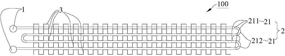
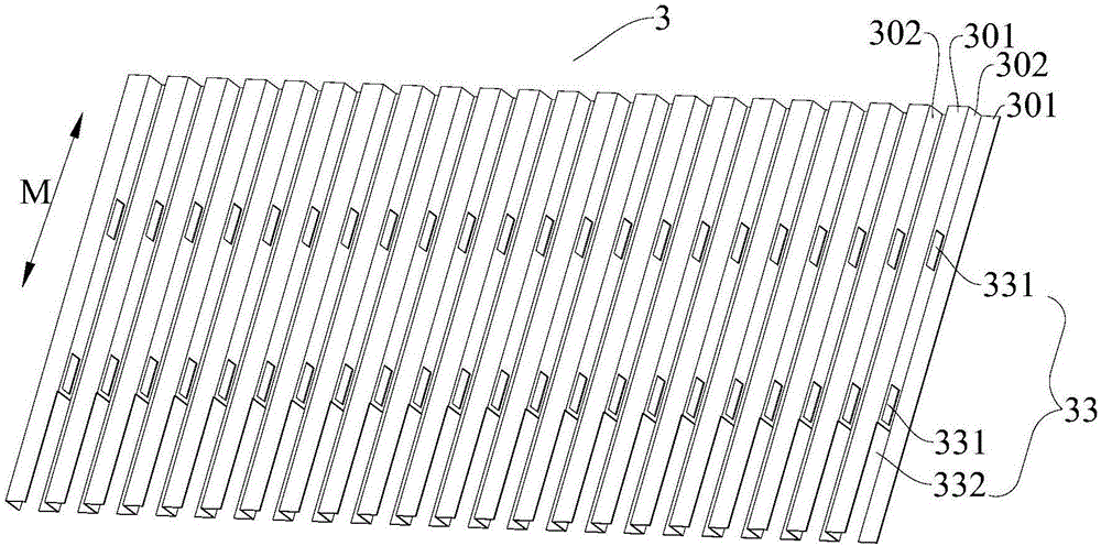
[0036] Refer below Figure 1-Figure 6 A microchannel heat exchanger 100 according to an embodiment of the present invention is described.

[0037] According to the microchannel heat exchanger 100 of the embodiment of the present invention, such as figure 1 and figure 2 As shown, the microchannel heat exchanger 100 includes: two headers 1, a plurality of heat exchange tubes 2 and at least one fin 3, and the two headers 1 are arranged in parallel. Both ends of the plurality of heat exchange tubes 2 are respectively connected to...


PUM

PropertyMeasurementUnit
Sizeaaaaaaaaaa
Sizeaaaaaaaaaa

Abstract

The invention discloses a micro-channel heat exchanger, a refrigerator and an air-cooled refrigerator. The micro-channel heat exchanger comprises two collecting pipes, a plurality of heat exchange tubes and fins, wherein the two collecting pipes are arranged in parallel. Two ends of the plurality of heat exchange tubes are connected to the two collecting pipes, respectively, the plurality of heat exchange tubes are bent along the length direction to form a plurality of pipe layers, and the open area of part of the heat exchange tubes are greater than that of the rest heat exchange tubes. Each of the fins is arranged between adjacent two pipe layers or on the outer side of the pipe layer in the outermost layer, each of the fins extends in a corrugated shape in the extension direction of each of the heat exchange tubes, each of the fins extends continuously in the extension direction of each of the collecting pipes, and ventilating holes are formed in each of the fins. The micro-channel heat exchanger disclosed by the invention solves the problems that the water hanging amount on the surfaces of the fins is relatively great and water cannot be thoroughly discharged, and the condition that obstinate ice is generated on the surface of the micro-channel heat exchanger to affect the heat exchange efficiency is avoided. In addition, the defrosting period can be prolonged, the refrigerant flows of the plurality of heat exchange tubes are uniform, and the heat exchange property is enhanced.

Description

technical field [0001] The invention relates to the field of refrigeration and heat dissipation equipment, in particular to a microchannel heat exchanger, a refrigerator, and an air-cooled refrigerator. Background technique [0002] The engineering development of micro-channel heat exchange technology stems from the demand for cooling of high-density electronic devices and heat transfer of micro-electromechanical systems. Due to its compact structure and high heat exchange efficiency, micro-channel technology was first obtained in the automotive air-conditioning industry in the domestic market. industrialized development. [0003] The refrigeration system using a new generation of natural refrigerant CO2 is a supercritical cycle, and the system pressure is very high. For example, in the air-conditioning system, the high-pressure working pressure of the system must be above 13MPa, and the design pressure must reach 42.5MPa, which puts forward very high requirements on the pr...

Claims


Application Information

Patent Timeline
IPC IPC(8): F25B39/00F25D11/00F25D17/06F25D21/14
CPCF25B39/00F25D11/00F25D17/062F25D21/14
Inventor 唐学强孟宪春任伟
Owner HEFEI MIDEA REFRIGERATOR CO LTD
Why Eureka
Try Eureka