
A preparation method for in-situ growth of three-dimensional graphene on the surface of spherical copper powder

An in-situ growth and graphene technology, applied in metal processing equipment, gaseous chemical plating, coating, etc., can solve the problems of graphene damage, orientation restriction, graphene agglomeration, etc., and achieve the effect of strengthening

Active Publication Date: 2018-06-12
TIANJIN UNIV
View PDF7 Cites 0 Cited by
  • Summary
  • Abstract
  • Description
  • Claims
  • Application Information

AI Technical Summary

Problems solved by technology

At present, many studies focus on mixing graphene sheet or reduced graphene oxide directly with copper powder to achieve the purpose of uniform mixing with metal powder, but this will cause graphene agglomeration and damage graphene.
In addition, due to the sheet-like two-dimensional structure, the orientations that graphene sheets can carry in composite materials are limited, and the reinforcing effect of graphene cannot be fully exerted.

Method used


Image

  • A preparation method for in-situ growth of three-dimensional graphene on the surface of spherical copper powder
  • A preparation method for in-situ growth of three-dimensional graphene on the surface of spherical copper powder
  • A preparation method for in-situ growth of three-dimensional graphene on the surface of spherical copper powder

Examples


Embodiment 1

[0037] Put polymethyl methacrylate and steel balls into a ball mill jar with a mass ratio of 1:15, and fill it with argon as a protective atmosphere. Go through low-speed short-time ball milling (400 rpm, ball milling 2h) in a planetary ball mill. Scanned photographs of spherical polymethyl methacrylate as Figure 1a As shown, the photo of polymethyl methacrylate after ball milling is shown in Figure 1b As shown, the surface of PMMA after ball milling is relatively rough, which is suitable for the adhesion of copper powder.

Embodiment 2

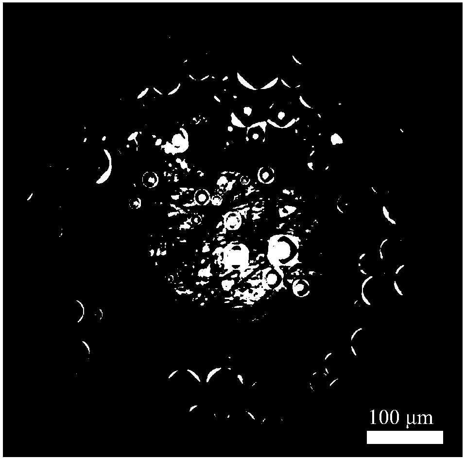
[0039] Put polymethyl methacrylate and steel balls into a ball mill jar with a mass ratio of 1:20, and fill it with argon as a protective atmosphere. Go through low-speed short-time ball milling (400 rpm, ball milling 2h) in a planetary ball mill. Scanned photographs of spherical polymethyl methacrylate as figure 2 As shown, at this time, due to the increase of the ball-to-material ratio, PMMA sticks and overlaps due to long-term impact during the deformation process, resulting in poor dispersion of PMMA, which is not conducive to subsequent mixing with copper powder. Example 3

Embodiment 3

[0040]Put polymethyl methacrylate and steel balls into a ball mill jar with a mass ratio of 1:10, and fill it with argon as a protective atmosphere. Go through low-speed short-time ball milling (400 rpm, ball milling 2h) in a planetary ball mill. Scanned photographs of spherical polymethyl methacrylate as image 3 As shown, the deformation and roughness of PMMA did not reach the ideal level at this time due to the decrease of the ball-to-material ratio.


PUM


Abstract

The invention relates to a preparation method for in-situ growth of three-dimensional graphene on the surface of spherical copper powder. Put polymethyl methacrylate and steel balls into a ball mill tank with a mass ratio of 1:10-20, and fill it with argon as a protective atmosphere after vacuuming; after ball milling, polymethyl methacrylate composite powder is obtained; The composite powder and nano-copper powder are mixed according to (0.1‑0.3): 10 and put into a tube furnace for in-situ chemical vapor phase reduction; the temperature is 800 °C, the reducing atmosphere is hydrogen, the protective atmosphere is argon, and the flow rates of hydrogen and argon The ratio is 1:2 to 2:1; the reduction time is 5 to 15 minutes; the carbon atoms generated by the decomposition of polymethyl methacrylate generate graphene on the copper surface, and the in-situ grown three-dimensional graphene-coated copper composite material is obtained. The invention utilizes a ball milling method and a powder metallurgy method to grow graphene in situ, and realizes the strengthening of the copper matrix material, and has good prospects for the application of high-strength copper materials in electronic devices.

Description

technical field [0001] The invention relates to a method for in-situ growth of a three-dimensional graphene-coated copper composite material by powder metallurgy using an in-situ chemical vapor reduction method, and belongs to the technical field of powder metallurgy. Background technique [0002] Copper is a material with good electrical conductivity, ductility and thermal conductivity, and is widely used in industries such as electrical, mechanical and national defense. The fly in the ointment is that the strength of copper is very low. In the application of electronic devices (such as PCB boards), the strength is not high enough to cause various problems, such as shortened lifespan and easy damage. With the development of society and the shortage of energy sources, people have more demands for lightweight and high-strength materials, and copper-based composite materials are an ideal material to meet these requirements. In the preparation of high-strength copper materials...

Claims


Application Information

Patent Timeline
Patent Type & Authority Patents(China)
IPC IPC(8): B22F1/00B22F1/02C23C16/26C23C16/44
CPCC23C16/26C23C16/4417B22F1/065B22F1/16
Inventor 赵乃勤杨昆明何春年师春生刘恩佐
Owner TIANJIN UNIV
Learn More