Steam mixer
A mixer and steam technology, applied in fluid mixers, mixers, mixing methods, etc., can solve problems such as poor mixing effects, and achieve the effects of easy maintenance, pressure shock relief, and simple manufacturing
- Summary
- Abstract
- Description
- Claims
- Application Information
AI Technical Summary
Problems solved by technology
Method used
Image


Examples
Embodiment 1
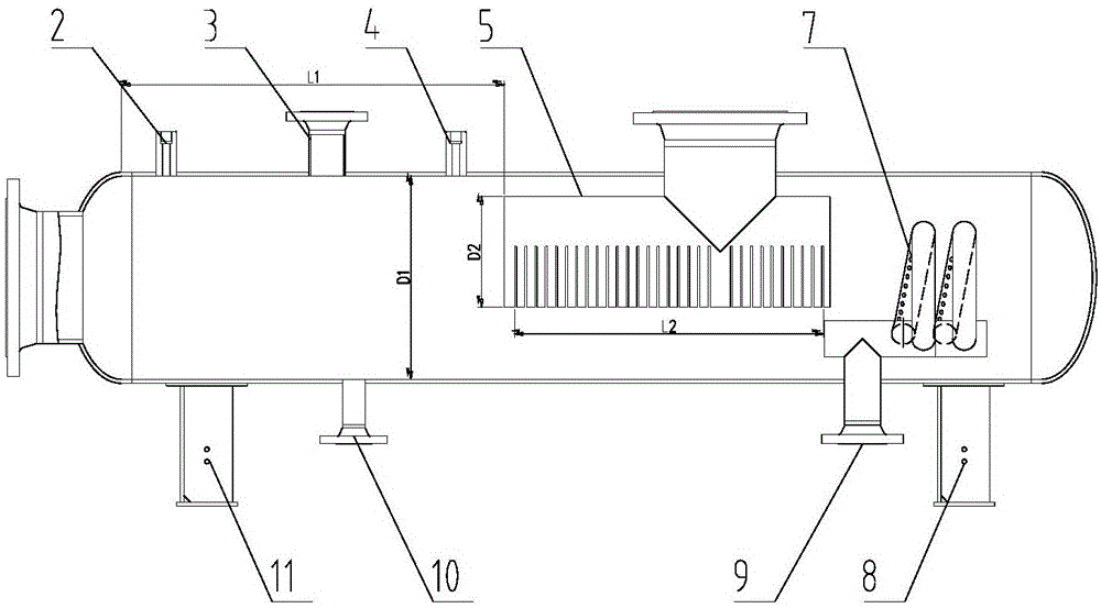
[0030] Such as figure 1 , figure 2 and image 3 As shown in the steam mixer, the top of one end of the heater shell is connected to the main steam pipe 6 through a flow regulating valve, the other end of the heater shell is connected to the mixed steam pipe 1 through a gate valve or a stop valve, and the main steam pipe 6 passes through a gate valve Or the cut-off valve is connected to the mixed steam pipe 1, and the bottom of the heater shell opposite to the main steam pipe 6 is connected to the heating steam pipe 9 through a flow regulating valve, and the connection between the main steam distribution pipe 5, the heating steam pipe 9 and the main steam pipe 6 Connecting pipes 15 are respectively provided, and the part of the connecting pipe 15 protruding from the main steam distribution pipe 5 and the heating steam pipe 9 is set as a hollow cylinder structure, and the part of the connecting pipe 15 extending in the main steam distribution pipe 5 and the heating steam pipe ...
Embodiment 2
[0034] On the basis of Example 1, different from Example 1, such as image 3 As shown, the steam mixer includes a heater shell, the main steam distribution pipe 5 is arranged laterally above the central axis of the heater shell, the end of the main steam distribution pipe 5 is sealed by a blocking plate 12, and the bottom of the main steam distribution pipe 5 Circular steam distribution holes 14 are provided, and strip-shaped steam distribution holes 13 arranged at equal intervals are arranged between adjacent circular steam distribution holes 14. The strip-shaped steam distribution holes 13 extend from the bottom of the main steam distribution pipe 5 to the The central axis of the main steam distribution pipe 5 is recessed and extended.
[0035] The circular steam distribution hole 14 is opened when the steam volume is relatively small, and the strip-shaped steam distribution hole 13 is opened when the steam volume is relatively large. The diameter of the circular steam distrib...
Embodiment 3
[0037] On the basis of Example 1, different from Example 1, such as Figure 4 , Figure 5 , Figure 6 and Figure 7 As shown in the steam mixer, the combined nozzle 7 includes a communication pipe 16 and a spiral distribution pipe 18. The spiral distribution pipe 18 is coiled on the communication pipe 16 at equal intervals in a spiral shape. The spiral distribution pipe 18 is set as a hollow annular pipe structure. Nozzles 17 are arranged at equal intervals in a ring on the inner ring side wall of the pipe 18 , and the end of the communication pipe 16 is sealed by a blocking plate 12 .
[0038] The nozzle 17 is set in a dumbbell-shaped structure that shrinks and expands gradually, its throat diameter d1 is not greater than 10mm, and the value of the throat width l should not be less than 0.5 times of the throat diameter d1, between the nozzle 17 on the spiral distribution pipe 18 and the spiral distribution pipe 18 A certain angle α is set, and the value of the angle α is s...
PUM
| Property | Measurement | Unit |
|---|---|---|
| diameter | aaaaa | aaaaa |
Abstract
Description
Claims
Application Information
 - R&D
- Intellectual Property
- Life Sciences
- Materials
- Tech Scout
- Unparalleled Data Quality
- Higher Quality Content
- 60% Fewer Hallucinations
Browse by: Latest US Patents, China's latest patents, Technical Efficacy Thesaurus, Application Domain, Technology Topic, Popular Technical Reports.
© 2025 PatSnap. All rights reserved.Legal|Privacy policy|Modern Slavery Act Transparency Statement|Sitemap|About US| Contact US: help@patsnap.com