
variable damping valve

A damping valve and variable technology, applied in servo motor components, mechanical equipment, fluid pressure actuating devices, etc., can solve the problem of inability to effectively meet the requirements of damping size, etc., to relieve pressure shock, suppress pressure shock, increase pressure damping effect

Active Publication Date: 2019-10-29
YANSHAN UNIV
View PDF10 Cites 0 Cited by
  • Summary
  • Abstract
  • Description
  • Claims
  • Application Information

AI Technical Summary

Problems solved by technology

From the above analysis, it can be seen that the current use of fixed damping can only compromise the above-mentioned problems, and cannot effectively meet the requirements of the above-mentioned different working conditions for the size of the damping

Method used


Image

  • variable damping valve

Examples


Embodiment Construction

[0019] The present invention will be further described below in conjunction with the accompanying drawings. In the description of the patent of the present invention, the directions indicated by "left", "right", "front", "back", "bottom", "horizontal" and "vertical" etc. The positional relationship is based on the orientation or positional relationship shown in the drawings, which is only for the convenience of describing the present invention and does not require that the present invention must be constructed and operated in a specific orientation, so it should not be construed as a limitation of the present invention.

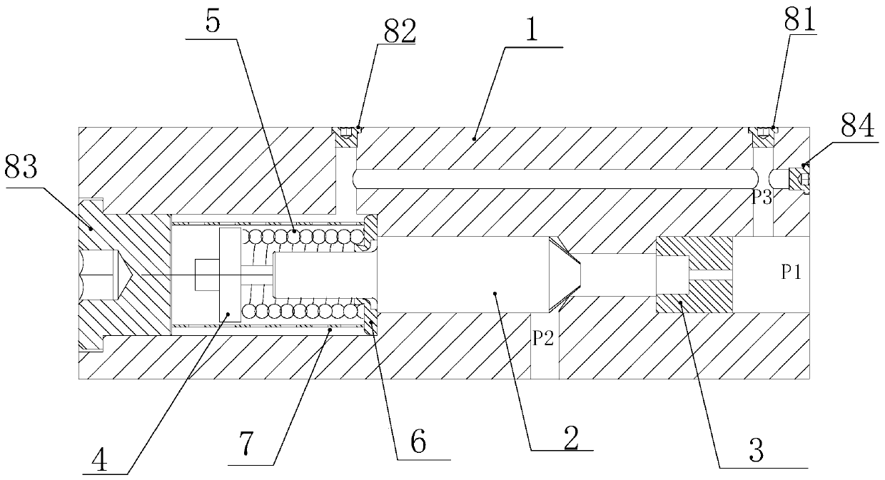
[0020] Such as figure 1 As shown, a variable damping valve includes a valve body 1, a valve core 2, a fixed damping hole 3, an adjusting screw 4, a return spring 5, a spring seat 6, a positioning sleeve 7, and screw plugs 81-84; the valve core 2 Located in the valve hole on the valve body 1, the bottom of the valve hole is a tapered hole, the main body of the...


PUM


Abstract

The invention discloses a variable damping valve. The variable damping valve comprises a valve body, a valve element, a fixed damping hole, an adjusting screw, a return spring, a spring base, a positioning sleeve and a screw plug; the right end part of the valve element is a conical surface; the bottom of a valve hole is a conical hole; the conical hole is used as a conical valve base matched withthe conical surface of the valve element; the conical surface of the valve element and the conical valve base form a throttling damping valve port; the return spring is positioned at the left end ofthe valve element through the adjusting screw and the spring base; the spring base is pressed to the bottom end surface of the spring cavity by the positioning sleeve; an oil inlet runner P1 and an oil outlet runner P2 on the valve body are distributed in an L form; the fixed damping hole is mounted in the oil inlet runner in front of the throttling damping valve port; and the spring cavity communicates with the oil inlet runner at the front end of the fixed damping hole through a runner P3. The variable damping valve can automatically adjust the damping magnitude according to the oil way pressure impact, so that the system unloading speediness is guaranteed, the unloading pressure impact is eliminated, and meanwhile, the pressure impact on a load feedback oil way can be effectively inhibited.

Description

technical field [0001] The invention belongs to the field of hydraulic valve design, and relates to a damping valve, in particular to a variable damping valve used in a three-way pressure compensator. Background technique [0002] The three-way pressure compensator is a key auxiliary component of the multi-way valve, and its performance directly affects the overall performance of the multi-way valve system. On the Ls oil circuit of the three-way pressure compensator, damping holes or damping valves are often set to stabilize the load feedback pressure and suppress pressure shocks. At present, the Ls oil circuit on the three-way pressure compensator is generally a fixed damping, that is, a damping valve type with a fixed damping hole or a fixed orifice. [0003] The damping on the Ls oil circuit has an important impact on the performance of the three-way pressure compensator. From the perspective of system unloading, the speed of the three-way pressure compensation valve spo...

Claims


Application Information

Patent Timeline
Patent Type & Authority Patents(China)
IPC IPC(8): F15B13/02
Inventor 赵丁选赵小龙樊晓璇陈夏非杨皓仁汤海龙
Owner YANSHAN UNIV
Learn More