
Transmission line foreign body removing device

A technology for removing power transmission lines and foreign matter, applied in the field of foreign matter devices, can solve the problems of long conveying pipes, low efficiency, and difficulty in ensuring strength, and achieve the effects of high degree of control automation, convenient and quick use, and thorough removal effect

Inactive Publication Date: 2016-12-07
LINQU POWER SUPPLY CO OF STATE GRID SHANDONG ELECTRIC POWER CO +2
View PDF8 Cites 4 Cited by
  • Summary
  • Abstract
  • Description
  • Claims
  • Application Information

AI Technical Summary

Problems solved by technology

[0007] This method of relying on hot air to melt ice has the following defects. The first is that the transmission line is generally assumed to be high in height, so a very long delivery pipe is required. It is difficult to ensure sufficient strength for a too long delivery pipe. If the strength is not enough, the nozzle Swaying from side to side, it is difficult to align the transmission line, and it is impossible to clean it in a directional manner. The second is that for high-voltage transmission lines, the supporting tower is more than ten meters or even tens of meters high, and it is impossible to clean up
[0008] In addition, the above two existing technologies are all aimed at cleaning a certain type of foreign matter, and cannot clean two kinds of foreign matter at the same time. For example, blade equipment cannot remove ice coating, and hot air equipment is specially designed for ice coating to remove foreign matter such as leaves and paper. The effect is not good and the efficiency is low, so a device that can remove two kinds of foreign matter at the same time is needed, and the removal efficiency is high, and the removal is clean and thorough

Method used


Image

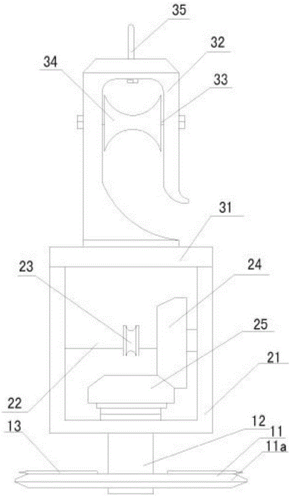
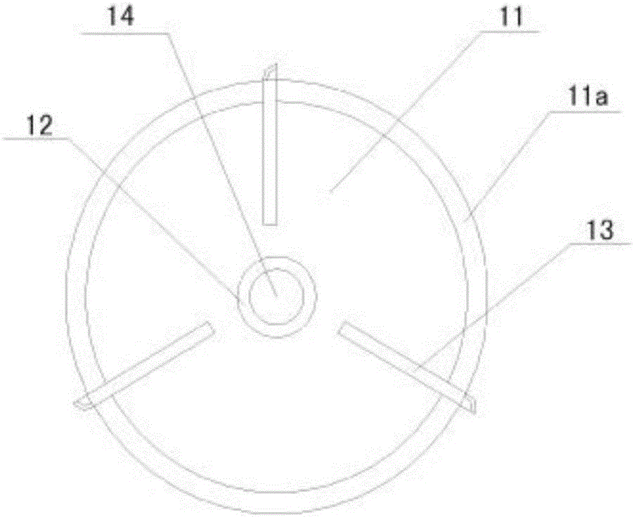
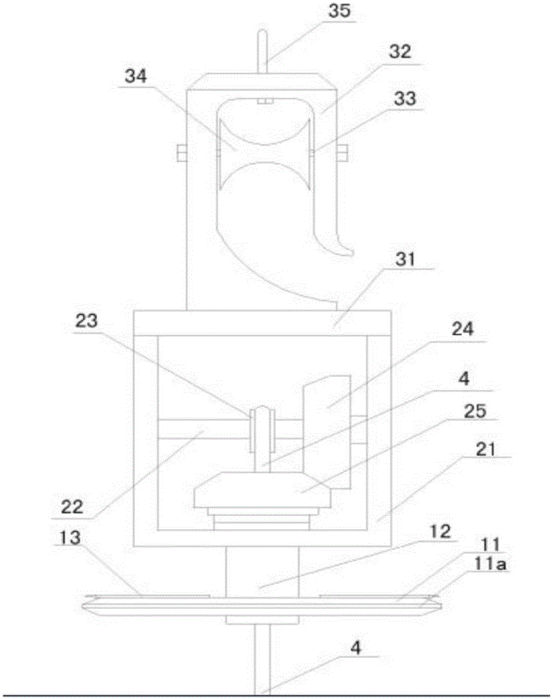
  • Transmission line foreign body removing device
  • Transmission line foreign body removing device
  • Transmission line foreign body removing device

Examples


Embodiment Construction

[0026]The present invention will be described in further detail below in conjunction with the accompanying drawings.

[0027] Such as Figure 5-8 As shown, the transmission line foreign matter removal device of the present invention includes a frame 1 , a roller 2 , a compressor 3 , a driving device 4 , a control device 5 and a camera 6 . The frame 1 includes a left-right symmetrical roller installation part 10 and an equipment installation part 11 in the middle, the roller 2 is installed on the roller installation part 10 of the frame 1 through the installation shaft, and the compressor 3 and the driving device 4 are fixedly installed side by side on the frame One side of the equipment installation part 11 of 1, the control device 5 and the camera 6 are fixedly installed side by side on the other side of the equipment installation part 11 of the rack 1, and the compressor 3, the driving device 4, and the camera 6 are all electrically connected to the control device 5. The co...


PUM


Abstract

The invention provides a transmission line foreign body removing device. The device comprises a rack 1, rolling wheels 2, a compressor 3, a driving device 4, a control device 5 and a video camera 6; the rack 1 comprises bilaterally symmetrical rolling wheel installation parts 10 and an equipment installation part 11 in the middle, the rolling wheels 2 are installed on the rolling wheel installation parts 10 of the rack 1 through installation shafts, the compressor 3 and the driving device 4 are fixedly installed on one side of the equipment installation 11 of the rack side by side, the control device 5 and the video camera 6 are fixedly installed on the other side of the equipment installation part 11 of the rack 1 side by side, and the compressor 3, the driving device 4 and the video camera 6 are electrically connected with the control device 5. According to the transmission line foreign body removing device, the blowing direction can be adjusted according to the positions of foreign bodies, the removing action of a three-dimensional space is achieved, directional removing is precise, the removing efficiency is high, the removing effect is thorough, the degree of control automation is high, and use is convenient and rapid.

Description

technical field [0001] The invention relates to a maintenance device used in power transmission lines, in particular to a device for removing foreign matter on the power transmission line, which can accurately locate and clean foreign matter, and has high cleaning efficiency and good effect. Background technique [0002] In today's society, electricity, as an indispensable energy source, plays an increasingly important role in social development. The transmission network is also spread all over the place. These transmission lines have been exposed to the natural environment for a long time. Due to the influence of man-made or natural factors, in Some foreign objects are often hung on the transmission line, which seriously affects the normal operation of the transmission line and causes transmission safety accidents. [0003] The foreign matter on the transmission line can be roughly divided into two categories. The first type is garbage foreign matter caused by man-made or n...

Claims


Application Information

Patent Timeline
Patent Type & Authority Applications(China)
IPC IPC(8): H02G1/02
CPCH02G1/02
Inventor 张洪亮赵明清徐长波许朋波
Owner LINQU POWER SUPPLY CO OF STATE GRID SHANDONG ELECTRIC POWER CO
Learn More