LED (light emitting diode) lamp using inductance voltage reduction

A technology of LED lamps and inductors, applied in electric light sources, electrical components, electroluminescent light sources, etc., can solve the problem of waste of alternating current, and achieve the effect of small DC impedance, large AC impedance, and reliable working performance.

Inactive Publication Date: 2016-11-23
周鸿德
View PDF15 Cites 0 Cited by
  • Summary
  • Abstract
  • Description
  • Claims
  • Application Information

AI Technical Summary

Problems solved by technology

[0002] The Chinese patent has disclosed the name: "Power supply for automatically stabilizing working voltage and current" (Patent No.: 2014106842959). This power supply can be used for LED lamps, and an AC input terminal of the rectifier stack adopts a capacitor step-down method to step down. The problem with this power supply is: when the alternating current is in the positive half cycle, the alternating current enters the rectifier stack through the capacitor step-down, and the direct current is output through the rectifier stack, and the direct current passes through the capacitor C 2 After filtering, flows through the LED R L , Zener diode VD, the output of the rectifier stack returns to the other end of the AC input, at this time, the light-emitting diode works and emits light
When the alternating current is in the negative half cycle, the alternating current will be directly input into the rectifier stack, and the rectifier stack will output direct current, and the direct current will pass through the capacitor C 2 Filtered stream to LED R L , the Zener diode VD enters the rectifier stack and outputs to the outside. At this time, the direct current cannot pass through the capacitor C 1 , only by resistor R 5 on through, because resistor R 5 The resistance value is very large, and the current flowing is very small, so when the alternating current is in the negative half cycle, the whole circuit basically does not work, and half of the alternating current cannot work and is wasted

Method used


Image

  • LED (light emitting diode) lamp using inductance voltage reduction

Examples


Embodiment Construction

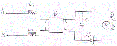
[0008] Such as figure 1 shown, the present invention includes a first inductor L 1 , the second inductor L 2 , rectifier stack D, capacitor C, voltage regulator diode VD and light-emitting diode R L , the first inductor L 1 , the second inductor L 2 They are respectively connected to the two AC input ends of the rectifier stack D.

[0009] The specific connection method is: the first inductor L 1 One end is AC input terminal A, and the other end is connected to pin 1 of rectifier stack D; one end of the second inductor L2 is AC input terminal B, the other end is connected to pin 2 of rectifier stack D, and pin 3 of rectifier stack D is connected to the positive pole of capacitor C And the positive pole of the light-emitting diode RL, the 4 feet of the rectifier stack D are connected to the negative pole of the capacitor C and the positive pole of the Zener diode VD, and the light-emitting diode R L The negative pole of the voltage regulator diode VD is connected to the n...


PUM


Abstract

The invention relates to an LED (light emitting diode) lamp using inductance voltage reduction. The LED lamp comprises a voltage stabilizing diode VD and a rectistack D, wherein the voltage stabilizing diode VD is connected in series with the LED lamp. The LED lamp is characterized in that the alternating current input end of the rectistack D is respectively connected with a first inductor L1 and a second inductor L2. The LED lamp has the advantages that the characteristics of the inductance are used; the alternating current impedance is high; the direct current impedance is small; inductors are connected in series in the power supply input end of the LED lamp; the voltage of the alternating current is reduced; a power supply suitable for LEDs to work is obtained; meanwhile, the direct current can also smoothly pass through the inductors to return the line; high heat cannot be generated when the inductors work; the work performance is reliable.

Description

technical field [0001] The invention relates to a lamp, in particular to an LED lamp which uses an inductance to reduce voltage. Background technique [0002] The Chinese patent has disclosed the name: "Power supply for automatically stabilizing working voltage and current" (patent number: 2014106842959). This power supply can be used for LED lamps, and an AC input terminal of the rectifier stack adopts a capacitor step-down method to step down. The problem with this power supply is: when the alternating current is in the positive half cycle, the alternating current enters the rectifier stack through the capacitor step-down, and the direct current is output through the rectifier stack, and the direct current passes through the capacitor C 2 After filtering, flows through the LED R L 1. The Zener diode VD returns to the other end of the AC input from the output of the rectifier stack. At this time, the light-emitting diode works and emits light. When the alternating current...

Claims


Application Information

Patent Timeline
Patent Type & Authority Applications(China)
IPC IPC(8): H05B33/08H05B44/00H05B45/30
CPCH05B45/40
Inventor 周鸿德
Owner 周鸿德
Why Eureka
Try Eureka