Flexible controllable clutch transmission

A technology for transmissions and clutches, applied in transmissions, belts/chains/gears, fluid transmissions, etc., can solve the problems of reduced comfort, frustration, and impact of transmission components, and avoid high heat, wear, and shifting The effect of fast downshift speed and simple shift control

Active Publication Date: 2019-12-13
TIANJIN SAIXIANG M&E ENG CO LTD
View PDF5 Cites 0 Cited by
  • Summary
  • Abstract
  • Description
  • Claims
  • Application Information

AI Technical Summary

Problems solved by technology

[0003] At present, most of the clutches of traditional automatic transmissions use friction plate clutches. Due to the large volume of friction plate clutches, the design and application range of related mechanical devices are greatly limited. For example: Honda's parallel shaft AT transmission, Due to the large volume of the clutch, this transmission can only achieve six gears, and more gears such as eight ATs cannot be designed and applied, because its volume is unacceptable
Although the planetary gear automatic transmission has been improved in volume, its structure is complex, especially the shift control of the transmission is cumbersome, and there are still many defects in use.
In addition, when the friction plate clutch is combined, it is a hard contact, which will have an impact on the transmission parts. For example, when it is applied to an automobile transmission, it will cause a sense of frustration, which will reduce the comfort of the car.
The shifting mechanism of the dual clutch transmission is complex, including shift forks and synchronizers, as well as complex hydraulic or electronic control systems. Although the transmission upshifts quickly, it will hesitate when downshifting.

Method used


Image

  • Flexible controllable clutch transmission
  • Flexible controllable clutch transmission
  • Flexible controllable clutch transmission

Examples


Embodiment Construction

[0022] Embodiments of the present invention will be further described below with reference to the accompanying drawings.

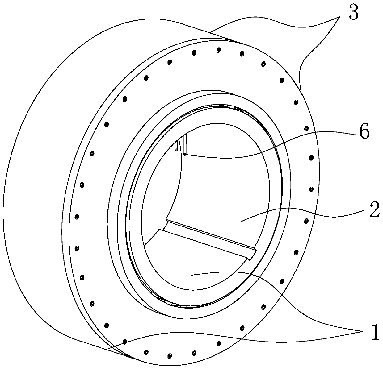
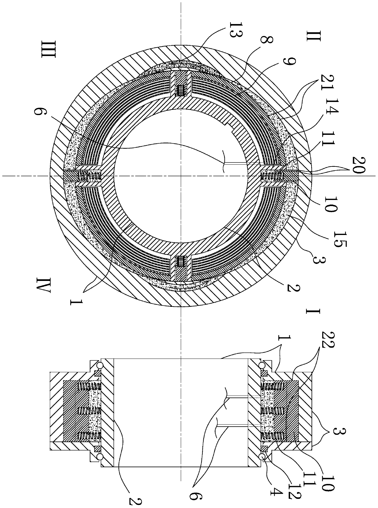
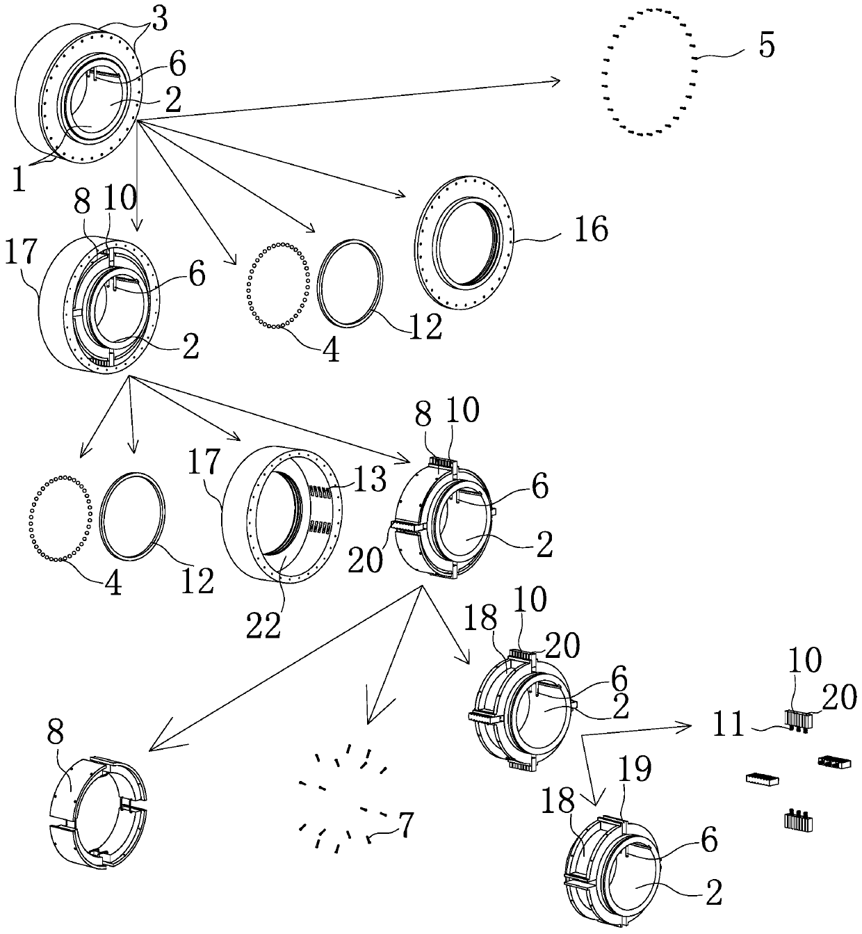
[0023] Such as Figure 1-9 As shown, a flexible controllable clutch transmission has: a flexible controllable clutch 1, a transmission gear 56, a transmission input shaft 31, a transmission output shaft 32 and a transmission housing 26, and is characterized in that the structure of the flexible controllable clutch 1 is : the passive sleeve 3 is socketed on the active sleeve 2, the outer cylindrical surface of the active sleeve 2 is provided with a blade 10 capable of radial movement and a blade movable groove 14, and a blade return spring 11 is arranged in the blade movable groove 14, The inner end faces 22 of the two axial end faces of the passive sleeve 3 are movably connected with the outer end faces of the blades 10 and the axial ends of the blade movable groove 14; The two end faces of the short axis of the surface are connected with the outer cylind...


PUM


Abstract

A flexible controllable clutch transmission is provided with flexible controllable clutches, a transmission gear, a transmission input shaft, a transmission output shaft and a transmission shell and is characterized in that according to the structure of each flexible controllable clutch, a driving sleeve is sleeved with a driven sleeve, the outer cylindrical face of the driving sleeve is providedwith blades capable of radially moving and blade movable grooves, and sealed wedge-shaped cavities are formed in the upper edge and the lower edge of the contact point of the cylindroid face of the driven sleeve and the outer cylindrical face of the driving sleeve and filled with magnetic (electric) rheological fluid, and the outer cylindrical face of the driving sleeve is provided with an electromagnet fixing groove and an electromagnet; the transmission input shaft and the transmission output shaft are sleeved with all-gear transmission gears and arranged into all-gear gear sets according toall-gear paired engagement; and each gear is provided with the corresponding flexible controllable clutch. The flexible controllable clutch transmission has the beneficial effects that the size is small, the impact resistance is high, the transmission efficiency is high, the structure is simple, no complex gear shifting mechanism is arranged, and gear shifting control is simple.

Description

[0001] Technical field [0002] The invention relates to an automatic transmission, which belongs to the technical field of mechanical transmission, in particular to a flexible controllable clutch transmission for road vehicles. Background technique [0003] At present, most of the clutches of traditional automatic transmissions use friction plate clutches. Due to the large volume of friction plate clutches, the design and application range of related mechanical devices are greatly limited. For example: Honda's parallel shaft AT transmission, Due to the large volume of the clutch, this transmission can only achieve six gears, and more gears such as eight ATs cannot be designed and applied, because its volume is unacceptable. Although the planetary gear automatic transmission has been improved in volume, its structure is complicated, especially the shift control of the transmission is relatively cumbersome, and there are still many defects in use. In addition, when the frictio...

Claims


Application Information

Patent Timeline
Patent Type & Authority Patents(China)
IPC IPC(8): F16H47/06F16H47/12
CPCF16H47/06F16H47/12
Inventor 不公告发明人
Owner TIANJIN SAIXIANG M&E ENG CO LTD
Why Eureka
Try Eureka