Improved ring shaped high-efficiency direct current arc welding machine

An arc welding machine, high-efficiency technology, applied in the field of arc welding machines, can solve the problems of the transformer current is too small, the primary coil current of the transformer is too large, and the transformer is easy to be damaged, so as to achieve good automatic current control, smooth pulsating voltage, and light weight Effect

Inactive Publication Date: 2008-08-06
黄汝明
View PDF0 Cites 0 Cited by
  • Summary
  • Abstract
  • Description
  • Claims
  • Application Information

AI Technical Summary

Problems solved by technology

The large current output by the secondary negative half cycle will make the primary coil current of the corresponding transformer also large, and generate high heat, and easily damage the transformer; at the same time, the current of the other transformer is too small, and the welding effect is not ideal.
[0005] Furthermore, the iron core of the existing arc welding machine is generally supported by splayed feet, the heat dissipation effect is not good enough, and the supporting feet are easy to contact with the coil and damage the coil, affecting the normal operation of the arc welding machine

Method used


Image

  • Improved ring shaped high-efficiency direct current arc welding machine
  • Improved ring shaped high-efficiency direct current arc welding machine
  • Improved ring shaped high-efficiency direct current arc welding machine

Examples


Embodiment 1

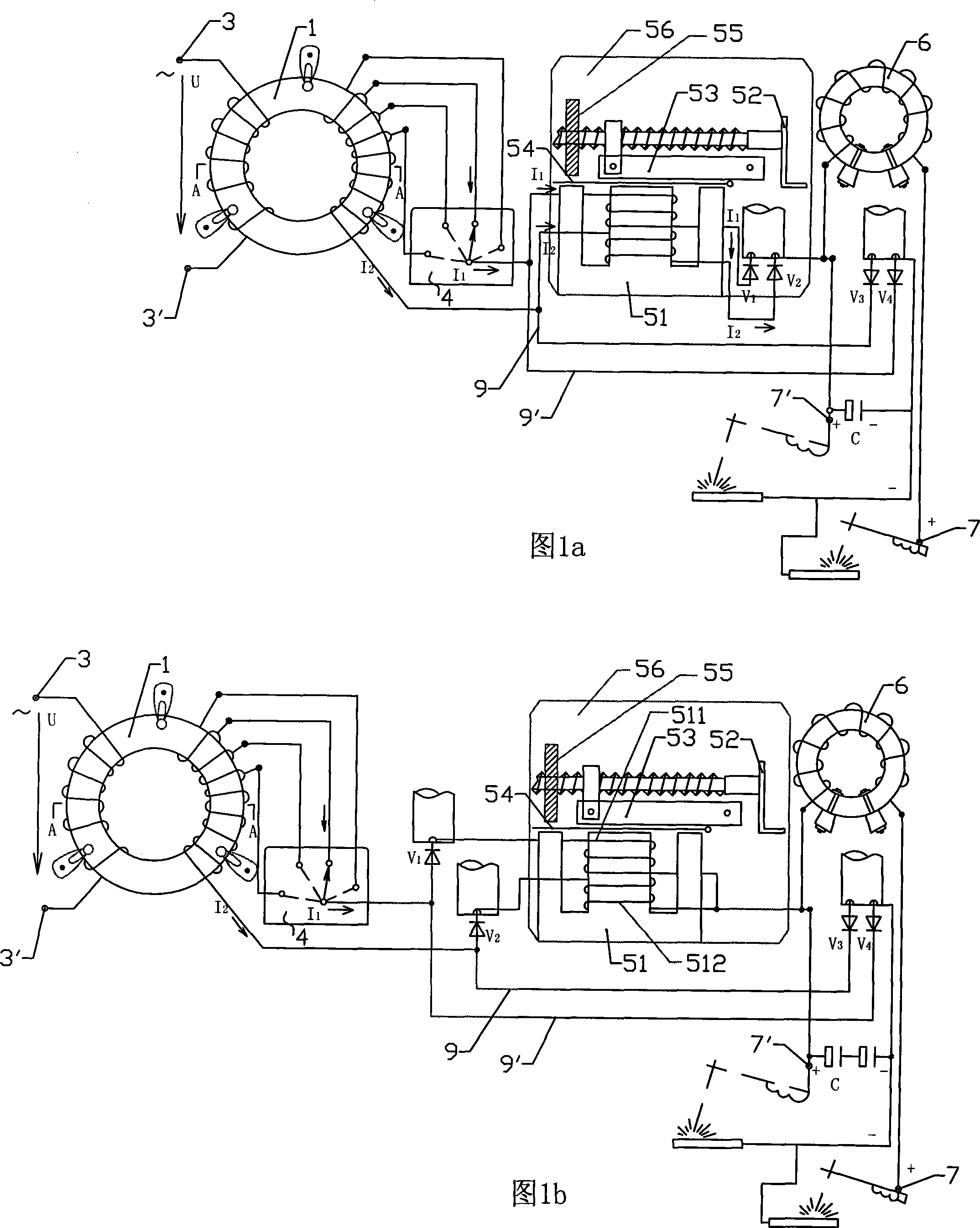
[0034] As shown in Figure 1a, this embodiment is a single-phase annular DC arc welding machine, and the reactor is connected between the output end of the annular transformer and the rectification circuit. The power supply input terminals 3, 3' are drawn from the two ends of the primary coil of the toroidal transformer, and the output terminals of the toroidal transformer are drawn from the secondary coil, wherein the lead wires of the output terminal of the positive half cycle are connected with the four input contacts of the voltage selection switch 4 in turn, from The winding wire 9' drawn from the output contact of the voltage selection switch 4 (that is, the lead wire of the positive half-axis output end of the transformer) and the lead wire 9 of the negative half-cycle output end of the toroidal transformer are respectively wound on the reactor core 51 in opposite directions, so that the reactor Two coils 511 and 512 wound in opposite directions are formed on the iron cor...

Embodiment 2

[0039] As shown in Fig. 1b, this embodiment is a single-phase annular DC arc welding machine, and two coils 511 and 512 wound in opposite directions on the reactor core are connected in series at the output end of the rectifier circuit. The structure and working principle of this embodiment are basically the same as those of Embodiment 1, except that the reactor is connected to the output end of the rectifier circuit, so no further description is given.

Embodiment 3

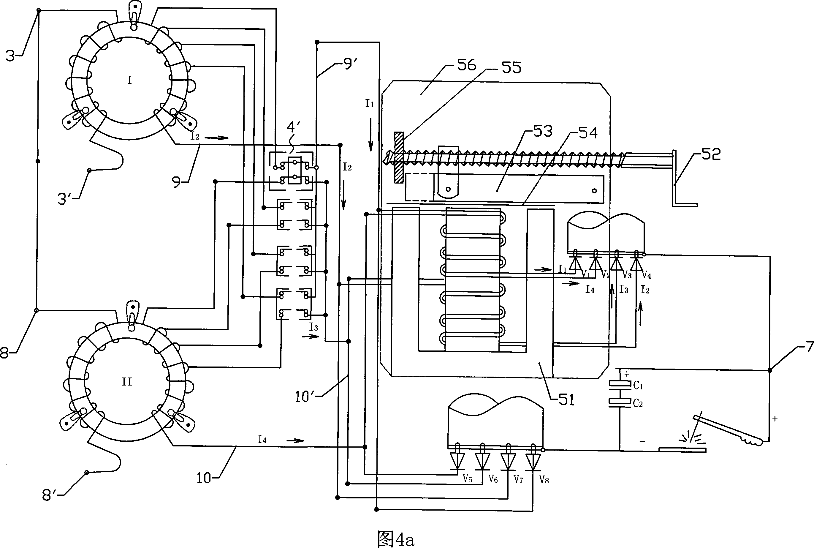
[0041] As shown in Figure 4a, this embodiment is a two-phase annular DC arc welding machine, and the reactor is connected between the output end of the toroidal transformer and the rectifier circuit; on the basis of Embodiment 1, a structure, material and winding are added For the same No. II toroidal transformer, another power supply input terminal 8, 8' is drawn from the primary coil of the toroidal transformer, and the output terminal of the transformer is similarly drawn from its secondary coil. The positive half-cycle output leads of the two transformers are connected to the input contacts of the voltage selection switch 4' one by one, and the output leads of the same level of voltage are connected to the same level of input contacts; at the output end of the voltage selection switch 4', the After the output contacts of the same group are connected in parallel, a winding wire is drawn out, which are the lead wire 9' of the positive half-cycle output end of No. I toroidal t...


PUM


Abstract

The invention discloses an improved ring efficient direct current arc welding machine, which comprises a ring transformer, a rectifier circuit and a filter capacitor. A power supply input terminal is extracted from primary coils of the ring transformer and an output terminal of the ring transformer is connected with the rectifier circuit. The invention is characterized in that the welding machine also comprises a reactor; an iron core of the ring transformer is circular plate-shaped and the rectifier circuit is a bridge pattern rectifier circuit; output signals of the ring transformer act on to-be-welded things after being treated by the rectifier circuit and the reactor and being filtered by the filter capacitor. Compared with the prior art, the welding machine is small in volume, light in weight and as high as 96 percent in efficiency. Additionally, output voltage of a positive half cycle and a negative half cycle of the ring transformer is connected respectively with two coils with opposite winding directions on the reactor after going through the rectifier circuit, thus leading the arc welding machine to have a better function of automatic current control without producing high heat and simultaneously leading rectified voltage ripples to be more gentle.

Description

technical field [0001] The invention relates to arc welding machine technology, in particular to an improved circular high-efficiency DC arc welding machine. Background technique [0002] At present, arc welding machines use AC mains as the working power supply. Since the frequency of AC mains is 50Hz, that is, the alternating current has 50 positive half cycles and negative half cycles within one second, so AC arc welding machines are used in the welding process. There will be one hundred ignition and flameout actions in seconds, and the welding performance is limited. However, if the DC arc welding machine is used, there will be no frequent ignition and flameout phenomenon, and the voltage and current waveform of the DC arc welding machine is relatively smooth, and the welding performance is superior to that of the AC arc welding machine. [0003] However, most of the existing DC arc welding machines are single-phase or three-phase, using a square iron core as the iron co...

Claims


Application Information

Patent Timeline
Patent Type & Authority Applications(China)
IPC IPC(8): B23K9/10H01F17/00H01F30/16
Inventor 黄汝明
Owner 黄汝明
Why Eureka
Try Eureka