
A large temperature difference cross-flow preheating pre-decomposition system and method thereof

A pre-decomposition and large temperature difference technology, applied in the direction of preheating costs, lighting and heating equipment, furnaces, etc., can solve the problems of not being able to adapt to the natural environment in high altitude areas, high power consumption of fans, difficult technical indicators, etc., to achieve improved gas-solid Effects of heat transfer rate, enhanced adaptability, and extended residence time

Active Publication Date: 2018-02-27
甘肃土木工程科学研究院有限公司
View PDF6 Cites 0 Cited by
  • Summary
  • Abstract
  • Description
  • Claims
  • Application Information

AI Technical Summary

Problems solved by technology

[0003] There are some inherent problems in the existing high-solid gas preheating decomposition technology. For example, the use of a double-series preheater system will make the structure complex, with many cyclones, large heat loss, and high power consumption of the fan. It is not suitable for small-scale It is used in cement production line; it is sensitive to coal quality, so it is difficult to adapt when using low-quality coal or anthracite as fuel; and it cannot adapt to the natural environment in high altitude areas, and it is difficult to achieve its corresponding technical indicators on a single series preheater

Method used


Image

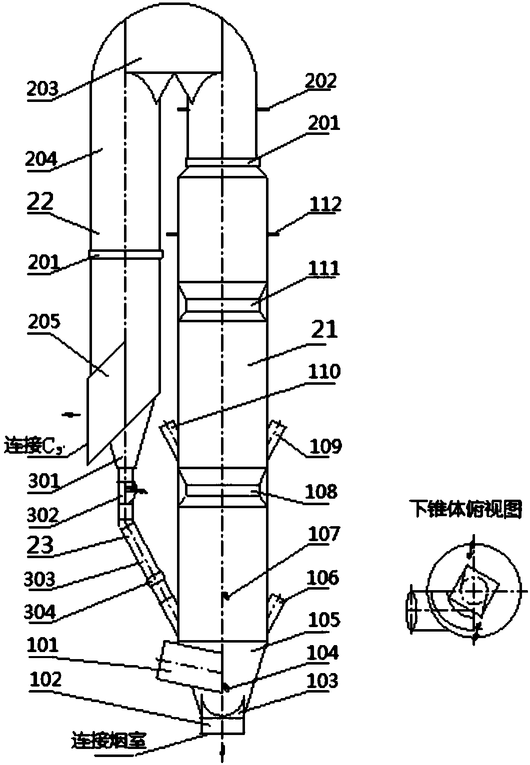
  • A large temperature difference cross-flow preheating pre-decomposition system and method thereof
  • A large temperature difference cross-flow preheating pre-decomposition system and method thereof
  • A large temperature difference cross-flow preheating pre-decomposition system and method thereof

Examples


Embodiment Construction

[0052] In order to make the objectives, technical solutions, and advantages of the present invention clearer, the following further describes the present invention in detail with reference to specific embodiments and drawings. However, those skilled in the art know that the present invention is not limited to the drawings and the following embodiments.

[0053] 1. Theoretical basis and principle of the present invention

[0054] 1. According to the law of thermodynamics, "heat is always spontaneously transferred from a high-temperature object to a low-temperature object. If there is a temperature difference between the two fluids, heat must be transferred". For the cement suspension preheating system, the heat transfer between the raw meal and the gas is convective heat transfer. According to the basic law of convective heat transfer-Newton's law of cooling, the heat flow of convective heat transfer is proportional to the temperature difference between the fluid and the solid wall...


PUM


Abstract

The present invention relates to a large temperature difference cross material flow preheating pre-decomposition system, which includes a cyclone preheater system, a decomposition furnace system and a kiln tail smoke chamber. The cyclone preheater system includes an N-level cyclone cylinder, except The other cyclones except the cyclone all include material distributing valves. The 1st level to the N-2nd level cyclones each send part of the material in the feeding port into the lower level cyclone through the material distributing valve, and send the other part of the material into the lower level cyclone through the material distributing valve. The flue gas temperature of the low-level cyclone is higher than that of the cyclone or calciner system; thereby increasing the gas-solid temperature difference in each cyclone and calciner system. The invention also relates to a method for preheating and pre-decomposing large temperature difference cross streams. The invention improves the heat exchange efficiency of the raw meal, reduces the temperature of the waste gas in the system, and improves the decomposition rate of the raw meal. It is suitable for the transformation of new and existing cement preheating and pre-decomposition systems, and can also be used for powder material heat exchange systems in metallurgy, chemical industry and other industries.

Description

Technical field [0001] The invention belongs to the technical field of thermal equipment in the cement industry, and specifically relates to a preheating and predecomposing system and a method for cross-flow preheating and predecomposing with large temperature differences. Background technique [0002] At present, the rapid development of new dry-process cement and the shortage of energy, it is imperative to use cheap low-quality bituminous coal or anthracite as the fuel for cement clinker calcination. In the production of new dry-process cement, the harmful components of raw fuel will cause hazards such as skinning in the calciner, and reduce the quality of mature materials and the operation rate of the system. As the core equipment of the calciner, how to reasonably arrange and match wind, coal, and materials in it, so that the fuel can be stably and completely burned in the calciner with a high raw material concentration, so that the temperature field in the furnace is uniform...

Claims


Application Information

Patent Timeline
Patent Type & Authority Patents(China)
IPC IPC(8): F27D13/00F27B7/20
Inventor 周应庆何忠茂韩军强彭嘉选强玉琴崔建勤
Owner 甘肃土木工程科学研究院有限公司
Learn More