
boom holding valve

A technology for maintaining valves and booms, which is applied in fluid pressure actuation devices, fluid pressure actuation system safety, mechanically driven excavators/dredgers, etc., and can solve problems such as shocks, easy shock vibrations, and complex manufacturing processes , to achieve the effect of simple overall structure, reliable overflow function and low processing cost

Active Publication Date: 2017-12-08
江苏盐高阀门制造有限公司
View PDF8 Cites 0 Cited by
  • Summary
  • Abstract
  • Description
  • Claims
  • Application Information

AI Technical Summary

Problems solved by technology

When the bucket is full of materials or the hook on the bucket is used to lift heavy objects, the automatic lowering of the working device often leads to accidents
At the same time, when the oil pipe bursts, the boom will suddenly drop, which poses a safety hazard
[0003] The patent publication number is CN101294402, and the invention patent titled "boom holding valve for hydraulic excavator" provides a boom holding valve. Although it can prevent the boom from falling naturally, it has the following disadvantages in engineering applications: (1) The valve stem that controls the lowering of the boom is a simple conical surface flow, the gradient of the flow area changes greatly, and the flow rate changes greatly in the control of the pilot handle, especially under heavy load, it is easy to produce shock vibration
In this case, the opening pressure of the relief valve is affected by the back pressure of the oil return, which cannot play a good role in safety protection; the damping hole is enlarged by the liquid flow for a long time, and the back pressure of the oil return of the relief valve decreases, and the valve stem cannot be opened. The reliability is poor; the overflow valve is opened by the taper surface of the valve stem. When the valve core is opened in the application, the overload pressure immediately drops (the opening area is too large), the boom sinks rapidly, and then suddenly closes to cause an impact
(3) All surfaces of the valve body need to be processed, and functional components are distributed on all surfaces of the valve body, the manufacturing process is complicated and the cost is high

Method used


Image

  • boom holding valve
  • boom holding valve
  • boom holding valve

Examples


Embodiment Construction

[0024] In order to make the purpose, technical solution and advantages of the present invention clearer, the exemplary embodiments of the present invention will be further described in detail below in conjunction with the accompanying drawings. Apparently, the described embodiments are only some of the embodiments of the present invention, and are not exhaustive of all the embodiments. Based on the embodiments of the present invention, all other embodiments obtained by persons of ordinary skill in the art without making creative efforts will fall within the protection scope of the present invention.

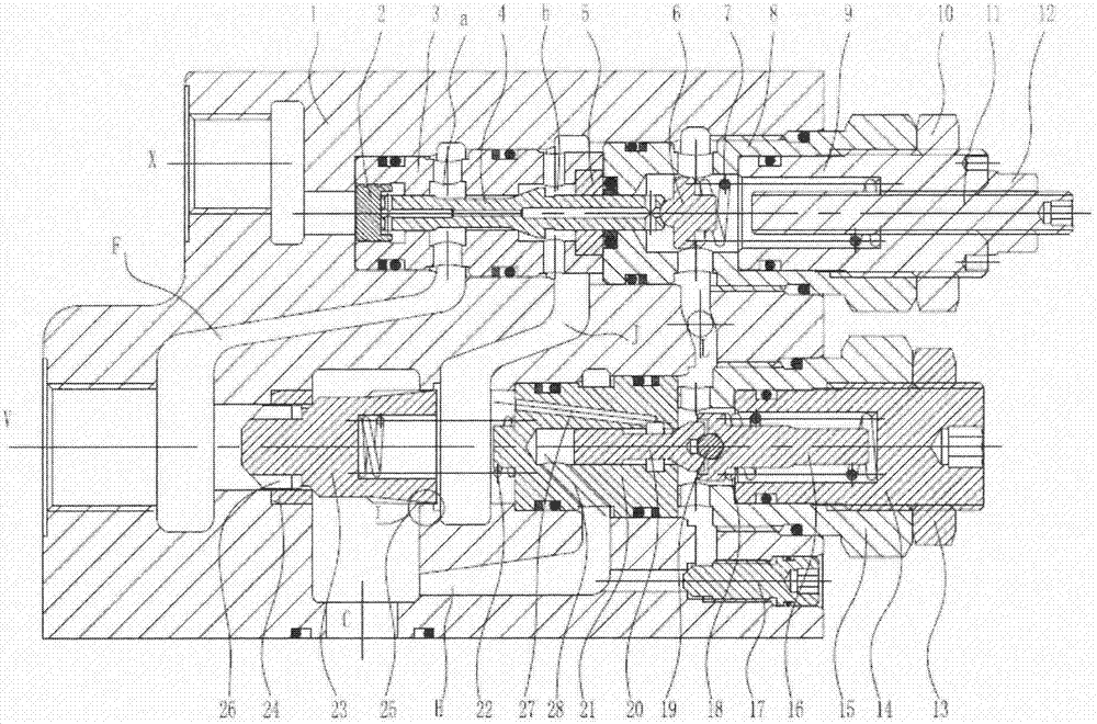
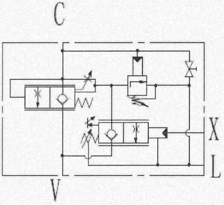
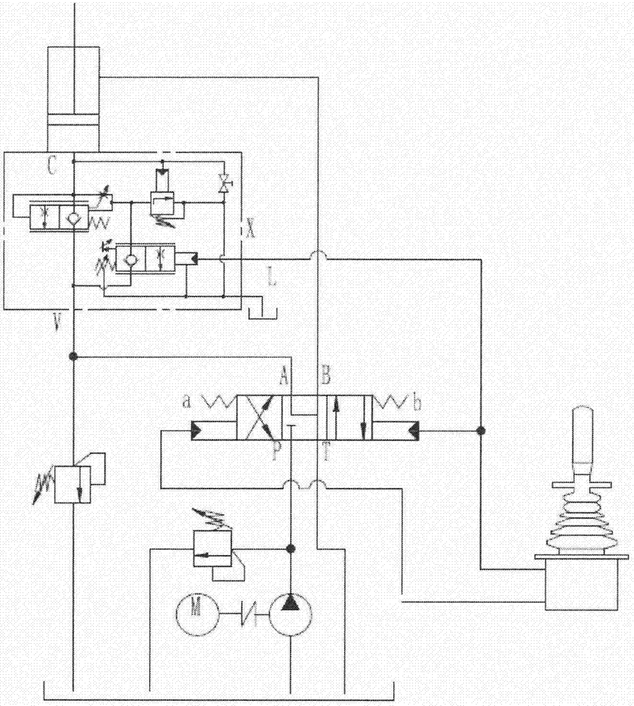
[0025] In one embodiment of the invention, a boom holding valve is provided, such as figure 1 and figure 2As shown, the boom holding valve mainly includes a valve body 1, a pilot mechanism (or pilot valve) installed in the valve body 1 or connected to the valve body 1, a main valve core 23, an overflow mechanism (or overflow valve) And emergency valve 17. In addition, an X po...


PUM


Abstract

The invention discloses a moving arm holding valve which comprises a valve body. A pilot mechanism, a main valve element and an overflow mechanism are arranged in the valve body. A channel F, a channel J, a channel L, a channel H, an oil opening X, an oil opening V and an oil opening C are formed in the valve body. When oil enters the oil opening V to enable the main valve element to overcome the acting force of a main spring to be opened, the oil opening V communicates with the oil opening C, and otherwise the main valve element is closed in a linear sealing manner, and the oil opening V does not communicate with the oil opening C. When oil enters the oil opening X to open the pilot mechanism, the oil opening C, a triangular groove of the main valve element, the channel J, the channel F and the oil opening V communicate; when the pilot mechanism is closed, the channel J and the channel F are cut off; when the overflow mechanism is opened, the oil opening C, the channel H and the channel L communicate; and otherwise the channel H and the channel L are cut off. According to the moving arm holding valve, when a moving arm operation rod of an excavator returns to the middle position, a moving arm can keep at the original position, and no shock is generated to moving arm control.

Description

technical field [0001] The invention relates to the technical field of control valves, in particular to a boom holding valve for a hydraulic excavator. Background technique [0002] For common hydraulic excavators, the boom hydraulic cylinder is directly connected to the boom control valve, and the boom control valve is directly used to control the rise, fall and maintenance of the boom. After the hydraulic excavator lifts the bucket off the ground, it may control the reversing valve of the boom or arm hydraulic cylinder to temporarily return to the neutral position due to various reasons, and the engine is in the idle state at this time. The gap between the valve core and the valve body is too large to cause leakage, and the working device will automatically descend under the action of its own weight. When the bucket is full of materials or the hook on the bucket is used to lift heavy objects, the automatic lowering of the working device often leads to accidents. At the s...

Claims


Application Information

Patent Timeline
Patent Type & Authority Patents(China)
IPC IPC(8): F15B13/02E02F3/43F15B20/00
CPCE02F3/43F15B13/02F15B20/005
Inventor 陈艳艳
Owner 江苏盐高阀门制造有限公司
Learn More