
Device and method for electrolytic processing of one-line flowing flexible protective sheath material in the whole process

A flexible flow, processing device technology, applied in electric machining equipment, electrochemical machining equipment, machining electrodes, etc., can solve the problem of not being able to more effectively reduce stray corrosion in machining areas, unfavorable machining stability and machining accuracy, and machining areas. stray corrosion and other problems, to achieve good cavitation, improve stability and machining accuracy, and reduce the degree of stray corrosion

Active Publication Date: 2018-02-06
NANJING UNIV OF AERONAUTICS & ASTRONAUTICS
View PDF12 Cites 1 Cited by
  • Summary
  • Abstract
  • Description
  • Claims
  • Application Information

AI Technical Summary

Problems solved by technology

But since there is still electrolyte entering the machined surface from the gap between the insulating cavity and the machined area, the machined area is still affected by stray corrosion
[0004] Although the traditional positive punching nesting electrolytic machining has the advantage of simple fixture design, its flow characteristics are diffuse flow, and there are obvious flow lines on the processing surface, which is not conducive to improving the stability and precision of processing; the flow channel at the inlet and outlet There is a large turning point, and the change of velocity and pressure is large; the uniformity of the flow field is poor, and cavitation is prone to occur; in addition, the existing methods for the protection of the processed area cannot effectively reduce the stray corrosion of the processed area.

Method used


Image

  • Device and method for electrolytic processing of one-line flowing flexible protective sheath material in the whole process
  • Device and method for electrolytic processing of one-line flowing flexible protective sheath material in the whole process
  • Device and method for electrolytic processing of one-line flowing flexible protective sheath material in the whole process

Examples


Embodiment Construction

[0018] The specific implementation manners of the present invention will be described in detail below in conjunction with the accompanying drawings.

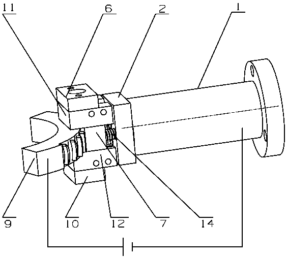
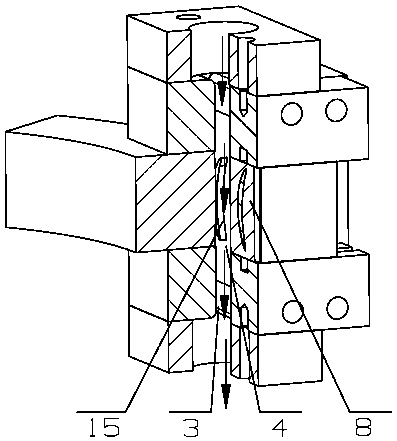
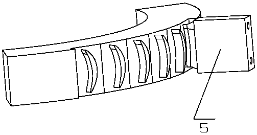
[0019] Implementation of the present invention - "the whole process of in-line flow flexible protective casing material electrolytic processing method and device", the device includes a cathode head, a flexible insulating block, a cathode body, a cathode tailstock, a cathode rod, a liquid inlet block, and a liquid outlet block , Upper pressing block, lower pressing block, front slider, rear slider, workpiece, stopper, spring.

[0020] The cathode head, cathode body, cathode tailstock and cathode rod are all made of conductive metal materials; the flexible insulating block is made of flexible non-conductive material; the liquid inlet block, liquid outlet block, upper pressing block, lower pressing block, and front slider , Rear slider, stopper are made of non-conductive material. The shape of the machined surface of the cathode ...


PUM


Abstract

The invention relates to an overall process linear flow flexible protection sleeve material electrochemical machining device and method, and belongs to the field of electrochemical machining. The device is formed by a cathode assembly and an auxiliary assembly. The flow mode of the electrochemical machining method is an overall process linear flow manner, electrolyte flows from the front edge of a blade to the back edge of the blade, and a flow field is in a convergence state; the cathode assembly moves and drives the auxiliary assembly to move at the same time, the electrolyte is supplied in a manner of aligning at a machining area all the time, and it is ensured that the flow field is stable; and in the electrochemical machining process, a flexible insulation block seals a machined area, and scattered corrosion caused by the fact that the electrolyte flows to the machined surface is effectively reduced. By means of the overall process linear flow flexible protection sleeve material electrochemical machining device and method, the sleeve material electrochemical machining flow field stability is better improved; the taper of the blade is reduced, and the machining accuracy is improved; and the surface quality is improved.

Description

technical field [0001] The invention relates to an electrolytic processing device and method for an in-line flowing flexible protective sheath material in the whole process, and belongs to the technical field of electrolytic processing. Background technique [0002] Electrolytic machining is based on the principle of electrochemical anodic dissolution to remove material and process the workpiece according to the shape and size of the tool cathode. Compared with other mechanical processing methods, electrolytic machining has the advantages of wide processing range, high processing efficiency, no loss of tools, and no mechanical cutting force. It has been widely used in aviation, aerospace, weapons, automobiles and other industries. [0003] In recent years, scholars and researchers at home and abroad have carried out a lot of research on electrolytic machining. In the patent "An electrode and processing method for electrolytic grooving of integral blisks" (application number...

Claims


Application Information

Patent Timeline
Patent Type & Authority Patents(China)
IPC IPC(8): B23H3/00B23H3/04
CPCB23H3/00B23H3/04
Inventor 朱栋柳傲谷洲之徐正扬刘嘉
Owner NANJING UNIV OF AERONAUTICS & ASTRONAUTICS
Learn More