
Electrocardiogram monitoring power supply control system based on electrocardio sensor

A technology of electric sensor and power supply control, which is applied in the fields of sensors, medical science, diagnostic recording/measurement, etc. It can solve the problems of insufficient transmission speed, bulky size, and high cost, and achieve simple operation interface, strong scalability, and high diagnosis value effect

Inactive Publication Date: 2016-11-23
李丽丽
View PDF6 Cites 4 Cited by
  • Summary
  • Abstract
  • Description
  • Claims
  • Application Information

AI Technical Summary

Problems solved by technology

However, most of these miniaturized products are black box type, that is, they can only be dynamically collected and stored, but cannot be displayed in real time on site.
[0005] The currently widely used ECG monitor based on the PC platform is bulky and inconvenient to move
Some people have also studied miniature ECG monitors and portable ECG monitors, but most of them are realized by low-grade single-chip microcomputers, and their functions are simple. They can only collect and display ECG signals, and cannot analyze real-time data.
Most of the telemetry ECG monitoring system and remote ECG monitoring system can only perform data collection and transmission on the client side, but cannot perform on-site data display and data analysis.
Moreover, the telemetry ECG monitoring system adopts short-distance wireless communication technology, which has the disadvantages of few centralized monitoring channels and limited distance; the remote ECG monitoring system uses a general-purpose microcomputer as the core, and uses a Modem to transmit data through a telephone line, which has the disadvantages that the transmission speed is not fast enough, Disadvantages such as not being able to transmit in real time for a long time, and high cost

Method used


Image

  • Electrocardiogram monitoring power supply control system based on electrocardio sensor
  • Electrocardiogram monitoring power supply control system based on electrocardio sensor
  • Electrocardiogram monitoring power supply control system based on electrocardio sensor

Examples


Embodiment Construction

[0019] Below in conjunction with accompanying drawing, technical scheme of the present invention is described in further detail:

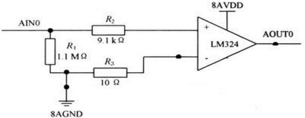
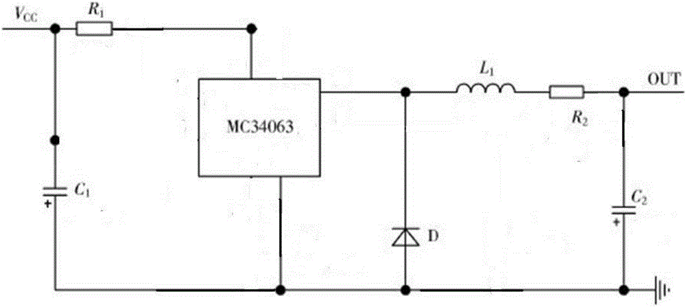
[0020] Such as figure 1 As shown, an ECG sensor-based ECG monitoring power supply control system includes a data acquisition terminal and a data monitoring terminal connected thereto. The data acquisition terminal includes an ECG sensor, an amplifier circuit, an analog-to-digital conversion module, and a microcontroller Module, display module, memory module, DSP module, wireless transmitter, power control module, power input module, rectifier circuit, voltage stabilizing circuit, described electrocardiogram sensor connects microcontroller through sequentially connected amplification circuit and analog-to-digital conversion module Module, the display module, memory module and power control module are connected to the corresponding ports of the microcontroller module, the microcontroller module is connected to the wireless transmitter through the DSP...


PUM


Abstract

The invention discloses an electrocardiogram monitoring power supply control system based on an electrocardio sensor. The system comprises a data collection terminal and a data monitoring terminal connected therewith, wherein the data collection terminal comprises an electrocardio sensor, an amplifying circuit, an analog-digital conversion module, a microcontroller module, a display module, a memory module, a DSP module, a wireless transmitter, a power control module, a power input module, a rectifying circuit and a voltage stabilizing circuit; the electrocardio sensor is connected with the microcontroller module through the amplifying circuit and the analog-digital conversion module in sequential connection; the display module, the memory module and the power control module are connected with corresponding ports of the microcontroller module; and the microcontroller module is connected with the wireless transmitter through the DSP module. The system disclosed by the invention integrates the advantages of existing electrocardiogram monitor and is small in volume and light in weight, has the advantages of concise operation interface, strong expandability and the like and realizes relatively high diagnosis value for various arrhythmias and heart diseases.

Description

technical field [0001] The invention relates to an electrocardiographic monitoring system, in particular to an electrocardiographic sensor-based power supply control system for electrocardiographic monitoring, which belongs to the field of monitoring and control. Background technique [0002] With the accelerated pace of life and the aging population, heart disease has become one of the major diseases that endanger human health and life. The ECG monitoring system provides an effective means for the diagnosis and treatment of heart disease patients, and is of great significance to the prevention and diagnosis of heart diseases. The present invention can satisfy patients to monitor ECG conveniently and quickly, and find abnormal conditions in time. And take effective measures to better protect people's health. [0003] With the deteriorating living environment and increasing life pressure, the incidence of chronic diseases is increasing day by day. Usually, the treatment for...

Claims


Application Information

Patent Timeline
Patent Type & Authority Applications(China)
IPC IPC(8): A61B5/0402A61B5/00
CPCA61B5/7203A61B5/7225A61B5/316A61B5/318
Inventor 李丽丽
Owner 李丽丽
Learn More