
Half-fixed and combined rock strain measuring device

A rock mass and strain testing technology, applied in the direction of mechanical solid deformation measurement, etc., can solve the problems of non-recyclable and repeated use, poor signal quality, complicated installation and debugging, etc., to achieve stable and reliable test signals, reduce test costs, and safe operation and installation convenient effect

Active Publication Date: 2014-01-08
武汉岩海工程技术有限公司
View PDF6 Cites 0 Cited by
  • Summary
  • Abstract
  • Description
  • Claims
  • Application Information

AI Technical Summary

Problems solved by technology

[0003] The aim is to propose a semi-fixed combined rock mass strain measuring device, which greatly improves the above-mentioned shortcomings of the embedded strain gauge and sliding micrometer in the test installation method, and not only retains the embedded strain gauge but can The advantages of long-term continuous and uninterrupted real-time monitoring can also avoid embedded strain gauges, complicated installation and debugging, low survival rate, non-recyclable and repeated use, poor signal quality or inaccuracy, and sliding micrometers cannot be used for long-term Continuous, real-time monitoring or test errors caused by temperature differences and damage to the contact surface of the measuring ring

Method used


Image

  • Half-fixed and combined rock strain measuring device
  • Half-fixed and combined rock strain measuring device
  • Half-fixed and combined rock strain measuring device

Examples


Embodiment Construction

[0023] best practice

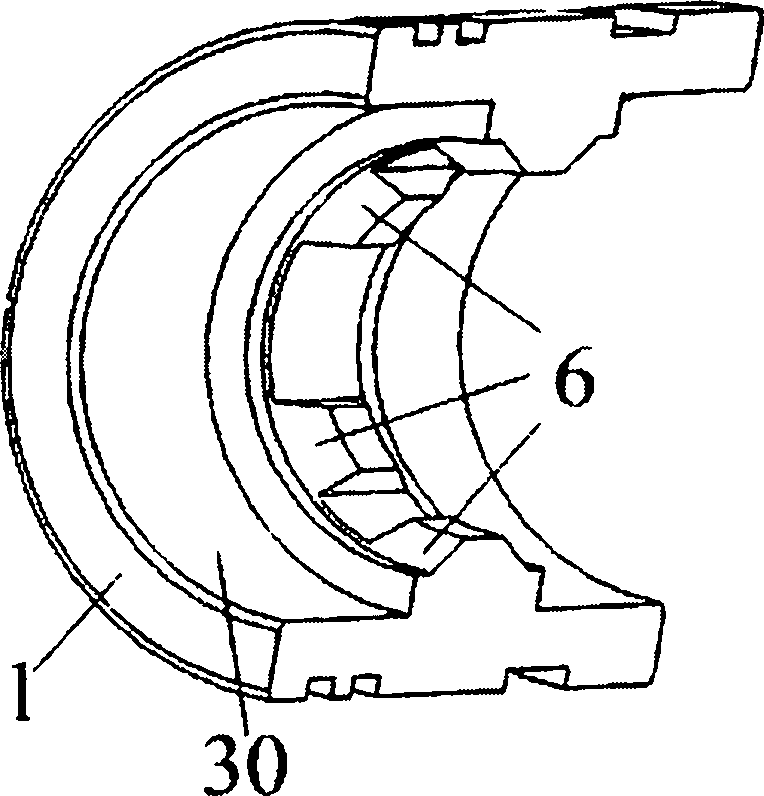
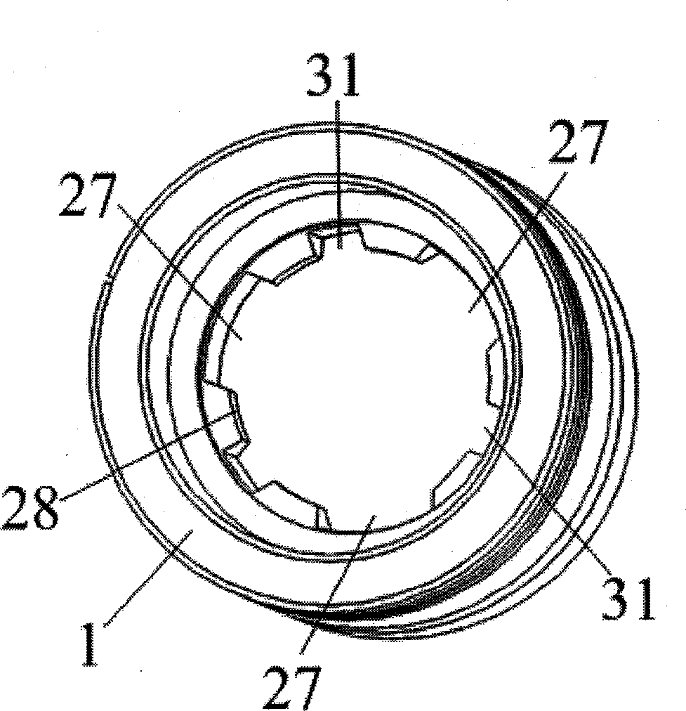
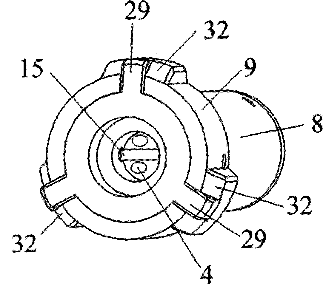
[0024] figure 1 , figure 2 Among them, (1) is the target ring, (2) is the support tube for the distance between the target ring, (3) is the independent strain test unit, (4) is the non-wired data communication transceiver, (5) is the strain reading buffer controller , (6) is in the middle of the axial position of the measuring ring, and its radial surface is equipped with two upper and lower conical seats facing away from each other, (7) is in the rock mass hole, (8) is an independent strain test The unit shell is supported, (9) is a spherical shape contact head at two axial ends of the independent strain test unit, (10) is a wireless communication antenna, and (11) is a strain reading buffer controller shell.

[0025] figure 1 , figure 2 Among them, the strain reading buffer controller (5) is outside the upper part of the rock mass hole, and a plurality of independent strain test units (3) can be arranged in sequence between each marking ring in t...


PUM


Abstract

The invention relates to a half-fixed and combined rock strain measuring device, which consists of measuring mark rings, a measuring mark ring space supporting tube, independent stain test units with non-wired data communication transceivers and a stain reading buffering controller, wherein the independent stain test units are combined and placed between adjacent measuring mark rings in a rock hole in turn respectively; the spherical contacts at the two ends of the shell each independent stain test unit are contacted and fixed with the upper and lower conical contact seat faces of adjacent measuring mark rings; and the end parts of the contacts at the two ends of the shell each independent stain test unit are provided with non-wired data communication transceivers respectively and face the non-wired data communication transceivers of adjacent independent stain test units end to end, the values of the strains sensed by the independent stain test units between the measuring mark rings are subjected to intra-unit electronic signal regulation and processing by a digital signal collection board first and then transmitted to the strain reading buffering controller outside the rock hole one by one from the inside to the outside by the non-wired data communication transceivers facing one another end to end under the control of software, and the strain reading buffering controller is connected with a computer in a wireless communication mode so as to transmit the strain values.

Description

Technical field [0001] The technical field of the present invention belongs to a technology for measuring rock mass strain. More specifically, the measuring ring is inserted into the geological hole or artificially reserved hole of the rock mass to be measured at a unit length interval through its support pipe and fixed by spraying. When the rock mass is subjected to its own gravity, external load, ambient temperature, etc. When the physical factors change, the distance between the measuring rings will change. By testing this change value, we call it the measurement technique of rock mass strain. The rock mass described here includes not only the rock mass in the concept of geology and geomorphology, but also all kinds of concrete engineering structures poured by hand. This strain measurement technique is widely used in geotechnical engineering. technical background [0002] Usually, the device for testing the internal strain of the rock mass is to use an embedded strain g...

Claims


Application Information

Patent Timeline
Patent Type & Authority Patents(China)
IPC IPC(8): G01B5/30
Inventor 程乐平程肯罗玉林胡聪崔文程红
Owner 武汉岩海工程技术有限公司
Learn More