
Ultrasonic plasticizing capillary rheometer and viscosity test method

A capillary rheometer and capillary technology, which is used in indirect flow characteristics measurement, instruments, flow characteristics, etc., can solve the problems of limited improvement in polymer fluidity, differences in test results, and lack of uniformity, and can improve the range of motion rates and Stability, reduce test error, simplify the effect of conveying path

Active Publication Date: 2016-11-16
CENT SOUTH UNIV
View PDF11 Cites 19 Cited by
  • Summary
  • Abstract
  • Description
  • Claims
  • Application Information

AI Technical Summary

Problems solved by technology

[0004] Because the above-mentioned patents only introduce ultrasonic waves into the heated and melted extruded polymers, the ultrasonic waves are mainly used to provide ultrasonic energy to the heated and melted polymers to enhance the fluidity of the melted polymers, but in the early stage Ultrasonic vibration is not added in the heating and melting process, so the improvement of polymer fluidity is limited, and different rheometers have different conditions such as the path that the melted polymer passes from the heating unit to the capillary die. Therefore, the test results of different rheometers will be different; and for the same rheometer, there may also be differences between test results in different periods due to changes in external conditions (such as ambient temperature) ; So far, there is no unified and widely recognized test standard at home and abroad

Method used


Image

  • Ultrasonic plasticizing capillary rheometer and viscosity test method
  • Ultrasonic plasticizing capillary rheometer and viscosity test method
  • Ultrasonic plasticizing capillary rheometer and viscosity test method

Examples


Embodiment Construction

[0049] The embodiments of the present invention will be described in detail below with reference to the accompanying drawings, but the present invention can be implemented in various ways defined and covered by the claims.

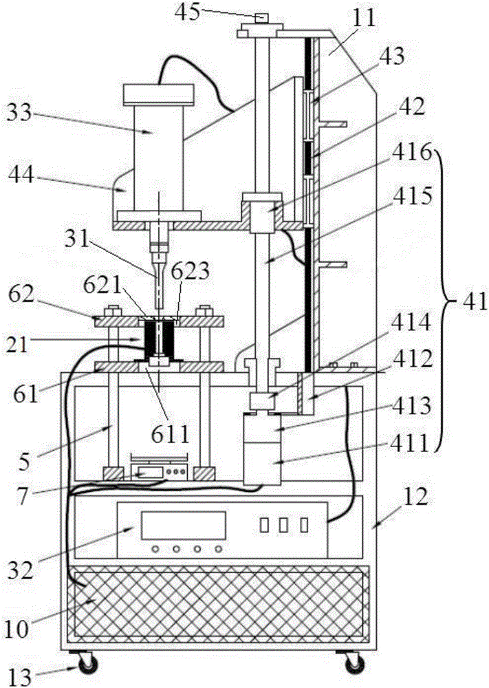
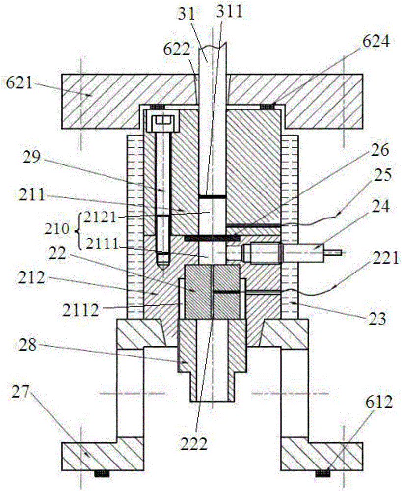
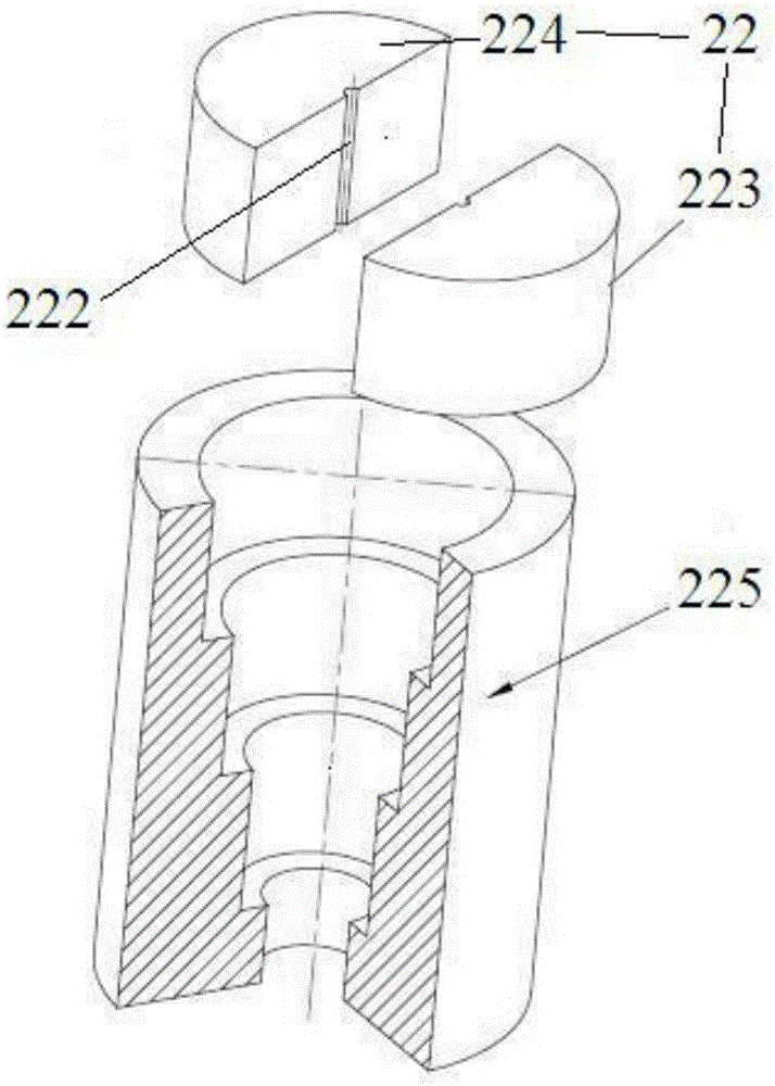
[0050] see Figure 1 ~ Figure 3 An ultrasonic plasticizing capillary rheometer comprises a frame and a rheological test unit, an ultrasonic vibration device, and a tool head motion loading unit respectively arranged on the frame, and the frame includes an upper frame (11) and a lower frame (12), the upper frame (11) is installed on the lower frame (12), and the bottom of the lower frame (12) is equipped with a running wheel (13), and the lower frame (12) is provided with a control cabinet (10), PLC The controller is arranged in the control cabinet (10), the ultrasonic generator (32) of the ultrasonic vibration device is installed on the lower frame and is positioned at the top of the control cabinet (10), the ultrasonic transducer (33) of the ultrasonic vi...


PUM


Abstract

An ultrasonic plasticizing capillary rheometer comprises a frame, a rheological test unit, an ultrasonic vibration apparatus, and a tool head moving and loading unit. The ultrasonic vibration apparatus is provided with an ultrasonic tool head capable of extending into a plasticizing chamber along an axial direction, providing extrusion force for polymer in the plasticizing chamber, and providing ultrasonic wave energy required by the polymer for fusion from a solid state to a liquid state. In the ultrasonic plasticizing capillary rheometer, three steps including heating fusion, ultrasonic vibration for fluidity increase, and material extrusion are completed through the ultrasonic tool head and in the plasticizing chamber, thereby simplifying the conveying path. A heating ring providing the required initial temperature for the plasticizing process sleeves a material canister, provides a constant material canister temperature for the rheometer, and reduces the test error. A filter screen is arranged in the material canister, centralizes fused polymer, and improves the test accuracy. During a test process, a viscosity test method is accurate in heating, short in fusion time, and wide in application range, is slightly affected by the external environment, and can provide viscosity data high in accuracy.

Description

technical field [0001] The invention relates to a technology for detecting rheological properties of polymer materials, in particular to an ultrasonic plasticizing capillary rheometer and a viscosity testing method. Background technique [0002] In recent years, with the vigorous development of micro-nano manufacturing technology, micro-injection molding technology based on polymer materials has been widely used in high-tech fields such as optoelectronic communication, image transmission, biochemical medicine, information storage, and precision machinery. Because the existing micro-injection molding machines mostly use screw or plunger plasticization methods, there is a problem that the amount of plasticization at one time is too large, and the injection amount seriously does not match the volume of the micro-parts, resulting in poor stability of molding quality and serious waste of materials. However, due to the different plasticizing methods, there are certain differences ...

Claims


Application Information

Patent Timeline
Patent Type & Authority Applications(China)
IPC IPC(8): G01N11/00
CPCG01N11/00G01N2011/006
Inventor 蒋炳炎齐鹏程刘弢吴旺青彭华建
Owner CENT SOUTH UNIV
Learn More