
A method of manufacturing a volute with a composite lining

A composite material and manufacturing method technology, applied in liquid fuel engines, components of pumping devices for elastic fluids, non-variable-capacity pumps, etc., can solve the problem that the size of the cavity between the impeller and the volute is difficult to precisely control, Affect the reliability of pumps, fans and compressors, reduce the efficiency of pumps, fans and compressors, etc., to achieve the effect of improving operating efficiency and reliability, avoiding deformation, and reducing roughness

Active Publication Date: 2018-04-17
GUANGDONG UNIV OF TECH
View PDF2 Cites 2 Cited by
  • Summary
  • Abstract
  • Description
  • Claims
  • Application Information

AI Technical Summary

Problems solved by technology

At present, the volute is mainly manufactured by casting, machining and other methods, which has the disadvantages of low precision and rough surface, resulting in a large and uneven gap between the impeller and the volute, and it is difficult to accurately control the size of the cavity between the impeller and the volute; When pumps, fans and compressors are running, gas or liquid backflow is easy to occur, which reduces the efficiency of pumps, fans and compressors, and also affects pressure and flow
At the same time, the inner surface of the volute is rough. When the gas or liquid flows at high speed, the resistance caused by friction increases significantly, which consumes the power of the driving motor and further reduces the efficiency of pumps, fans and compressors.
At the same time, the heat generated by friction will increase the temperature of pumps, fans and compressors, affecting the reliability of pumps, fans and compressors

Method used


Image

  • A method of manufacturing a volute with a composite lining
  • A method of manufacturing a volute with a composite lining
  • A method of manufacturing a volute with a composite lining

Examples


Embodiment 1

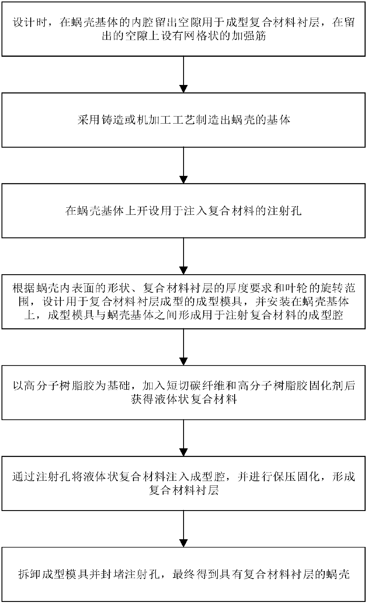
[0038] The invention also discloses a method for manufacturing a volute structure with a composite material liner 120. The volute with a composite material liner 120 manufactured by this method is used in pumps, fans and compressors, which can significantly reduce internal Gas or liquid flow resistance, improving the efficiency and reliability of pumps, fans and compressors, such as figure 1 As shown, the specific steps of the method are as follows:

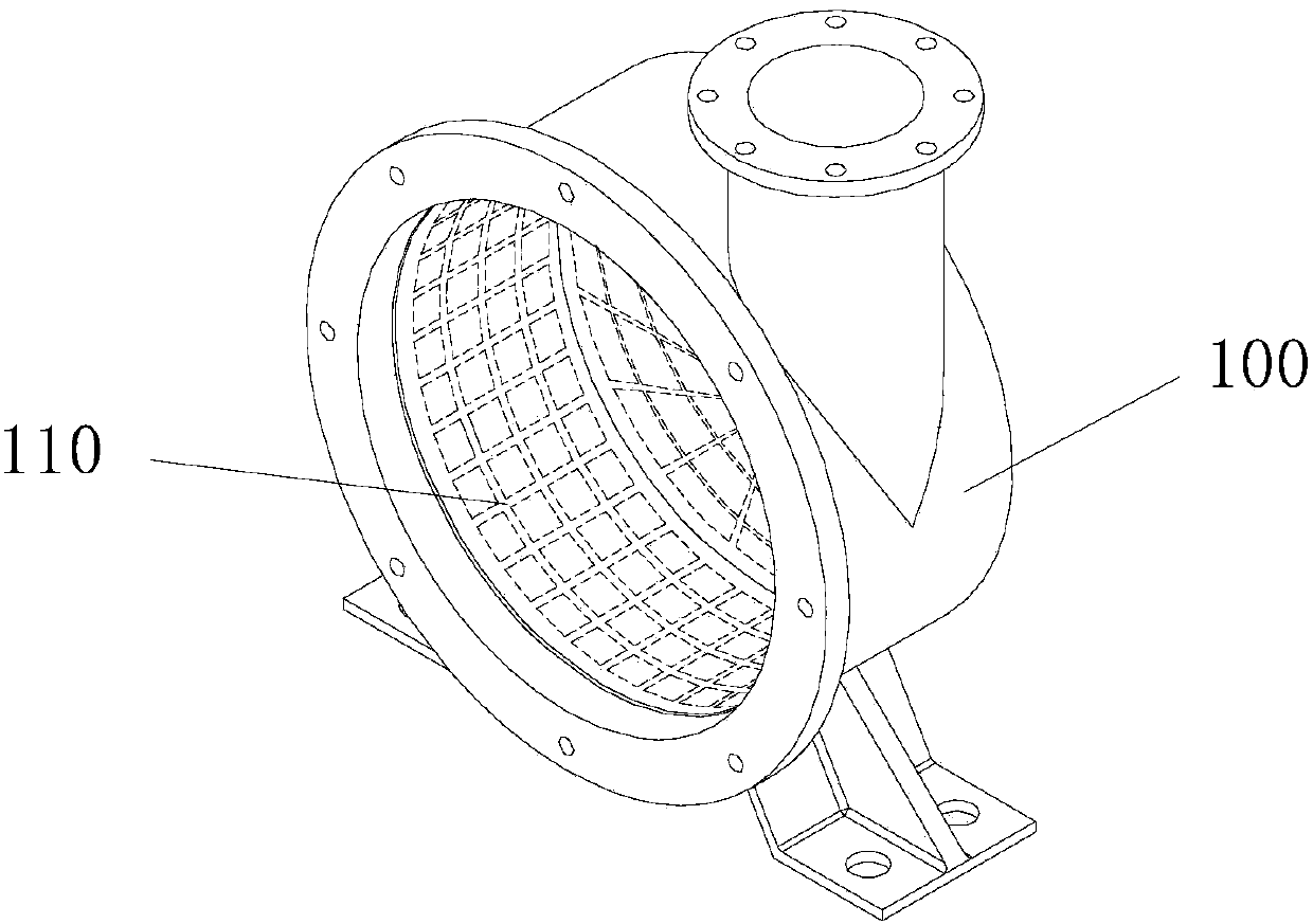
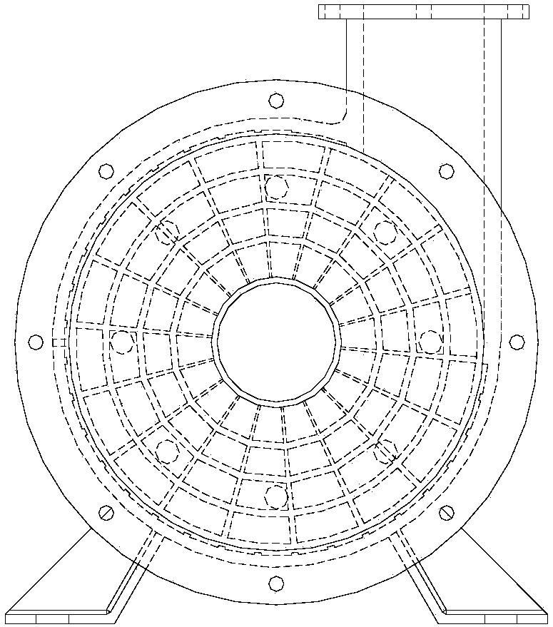
[0039] Step S1: Combine Figure 2 to Figure 5 As shown, according to the shape and structure requirements of the volute, the shell of the volute base 100 is designed, and a gap of 2-4 mm is designed at the part where the cavity is formed between the shell of the volute and the impeller, and the gap is used to form a composite lining 120; in addition, a grid-shaped reinforcing rib 110 with a thickness of 1-2 mm is designed at the same time, and the shape and size of other parts of the volute remain unchanged.

[0040]Step S2: Pr...


PUM

PropertyMeasurementUnit
thicknessaaaaaaaaaa
diameteraaaaaaaaaa
thicknessaaaaaaaaaa

Abstract

The invention discloses a manufacturing method for a volute with a composite lining. The manufacturing method includes the steps reserving a gap in a cavity of a volute base body and arranging latticed reinforcing ribs; manufacturing the volute base body and forming an injection hole; designing a forming mold for forming the composite lining and a sealing mold and installing the forming mold and the sealing mold on the volute base body; adding short carbon fibers and macromolecular resin adhesive curing agents with macromolecular resin adhesives as a base body and then obtaining liquid composite material; injecting the liquid composite material into a forming cavity through the injection hole and carrying out pressure maintaining and solidifying; and disassembling the forming mold, blocking the injection hole and obtaining the volute with the composite lining. The manufacturing method is simple, the operation is convenient, the roughness of the cavity of the volute base body can be effectively lowered, the shape and the dimension of the cavity of the composite lining of the volute can be accurately controlled, and the operation of an impeller is reliable and efficient.

Description

technical field [0001] The invention relates to the field of volute manufacturing, in particular to a method for manufacturing a volute with a composite lining. Background technique [0002] Pumps, fans and compressors are typical fluid machines that increase the pressure of gas or liquid and transport gas or liquid. The pump casing of the pump, the casing of the fan and the compressor (collectively referred to as the volute) and the impeller are the key parts of the pump, fan and compressor. The volute is the base, and the impeller is installed in the volute. The cavity formed between the impeller and the volute sucks gas or liquid at the gas or liquid inlet. With the rotation of the impeller, the position and volume of the cavity change, and the pressure of the gas or liquid is raised and transferred to the gas or liquid outlet to realize gas or liquid delivery. [0003] The precise dimensioning of the cavity between the impeller and volute has a significant impact on th...

Claims


Application Information

Patent Timeline
Patent Type & Authority Patents(China)
IPC IPC(8): B29C45/14F04D29/42
CPCB29C45/14B29C2045/14237F04D29/42
Inventor 章争荣程永奇肖小亭张鹏廖恒斌
Owner GUANGDONG UNIV OF TECH
Learn More