Gas liquefaction device with compression heat recovery function and liquefaction method thereof

A liquefaction device and heat recovery technology, applied in the field of gas cryogenic liquefaction, can solve the problems of conventional gas liquefaction devices such as high energy consumption, waste of compression heat, consumption of large circulating water, etc., achieve good social and economic benefits, and reduce energy consumption , the effect of low energy consumption

Active Publication Date: 2016-11-09
四川蜀道装备科技股份有限公司
View PDF5 Cites 9 Cited by
  • Summary
  • Abstract
  • Description
  • Claims
  • Application Information

AI Technical Summary

Problems solved by technology

[0003] The compression heat of the conventional gas liquefaction plant is taken away by the circulating water, and then recycled after being cooled by the circulating water ...

Method used


Image

  • Gas liquefaction device with compression heat recovery function and liquefaction method thereof
  • Gas liquefaction device with compression heat recovery function and liquefaction method thereof
  • Gas liquefaction device with compression heat recovery function and liquefaction method thereof

Examples


Embodiment 1

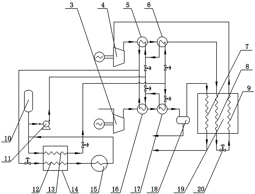
[0042] like figure 1 As shown, a gas liquefaction device with compression heat recovery includes a raw material gas treatment system, a refrigerant treatment system, and a compression heat recovery system;

[0043] In this embodiment, the raw gas treatment system includes a raw gas compressor 3, a raw gas normal temperature water cooler 16, a raw gas low temperature water cooler 17, a raw gas purification unit 18 and a gas liquefaction heat exchanger 19, wherein , the raw material gas input pipeline is connected with the raw material gas compressor 3, the raw material gas compressor 3 is communicated with the raw gas normal temperature water cooler 16, and the raw material compressor 3 is connected with a raw material gas supply pipeline, in the present embodiment, the described The feed gas is one or more of oxygen, nitrogen, hydrogen, natural gas liquefaction or liquid air separation. The feed gas normal temperature water cooler 16 is connected with the feed gas low temperat...

Embodiment 2

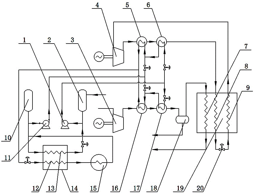
[0064] like figure 2 As shown, the device of this embodiment is substantially the same as that of Embodiment 1, the difference is that a low-temperature pipe is also provided on the pipeline communicating with the water inlet pipe of the refrigerant room temperature water cooler 5 and the raw material gas room temperature water cooler 16 water inlet pipe. The water tank 2 and the low-temperature water pump 1 are on the pipeline, with the low-temperature water delivery direction as the front, the low-temperature water pump 1 is located downstream of the low-temperature water tank 2, and the low-temperature water tank 2 can be replenished with low-temperature water through a low-temperature water supply pipeline , to ensure the continuous supply of low-temperature water, so that the low-temperature water can be continuously sent to the liquefaction device, and can also be sent during peak or peak electricity prices, and low-temperature water can also be taken by a compression re...


PUM


Abstract

The invention discloses a gas liquefaction device with a compression heat recovery function. The gas liquefaction device comprises a feed gas treatment system, a refrigerant treatment system and a compression heat recovery system. The invention further discloses a liquefaction method of the gas liquefaction device with the compression heat recovery function. The liquefaction method includes the process steps of feed gas compression cooling, feed gas liquefaction, refrigerant compression, refrigerant liquefaction, refrigerant reheating, heat transport fluid cooling, and supply of normal temperature water and low temperature water. The gas liquefaction device with the compression heat recovery function and the liquefaction method thereof have the beneficial effects that the low temperature water is obtained by recovering compression heat, and thus the energy consumption of the liquefaction device is substantially reduced; a low temperature water tank can also be used for cold accumulation, the low temperature water or ice can be obtained extra according to an electricity price difference, the low temperature water can be fed only at the pinnacle or peak time of electricity price, and the energy consumption of the liquefaction device is further reduced; and operation is easy, the energy consumption is low, the general trends of saving energy and reducing consumption are met, and social benefits and economical benefits are good.

Description

technical field [0001] The invention relates to the technical field of gas cryogenic liquefaction, in particular to a gas liquefaction device with compression heat recovery and a liquefaction method thereof. Background technique [0002] The volume of cryogenic liquid products (liquid oxygen, liquid nitrogen, liquid argon, liquid hydrogen and LNG, etc.) is small (such as 1m 3 The liquid oxygen is equivalent to 800Nm 3 Oxygen, such as 1m 3 of liquid hydrogen equivalent to 788Nm 3 Hydrogen, 1m 3 of LNG equivalent to 600Nm 3 Natural gas), which is convenient for long-distance transportation and has a wide radiation area. At the same time, when liquid hydrogen and LNG are used as vehicle fuels, the mileage is longer. Therefore, liquefaction plants producing liquid products play a very important role in industry. [0003] The compression heat of conventional gas liquefaction equipment is taken away by circulating water, and then recycled after being cooled by a circulating ...

Claims


Application Information

Patent Timeline
IPC IPC(8): F25J1/02
CPCF25J1/0015F25J1/0017F25J1/002F25J1/0022F25J1/0052F25J1/0227F25J1/0242F25J1/0297F25J2220/64F25J2230/04F25J2230/30F25J2270/906F25J1/0202F25J1/0259F25J1/0268F25J1/0279
Inventor 曹卫华
Owner 四川蜀道装备科技股份有限公司
Why Eureka
Try Eureka