Traction substation busbar potential transformer on-line monitoring automatic apparatus

A traction substation, bus voltage technology, applied in the direction of measuring devices, instruments, measuring electrical variables, etc., can solve the problems of long recovery time, abnormal bus voltage, large influence range, etc., to achieve convenient site, reasonable design, practicality strong effect

Active Publication Date: 2016-10-26
李彦吉 +1
View PDF6 Cites 3 Cited by
  • Summary
  • Abstract
  • Description
  • Claims
  • Application Information

AI Technical Summary

Problems solved by technology

[0004] 1) After the operating voltage transformer fails, it cannot be switched to the backup voltage transformer immediately, causing the main transformer to malfunction due to the low-voltage starting overcurrent protection; Power failure, large impact area and long recovery time;
[0005] 2) There is no backup YH secondary voltage monitoring device, and when there is a backup YH failure, after YH switching, the feeder impedance protection will cause false tripping;
[0006] 3) After the direct resistance of the fuse increases, the bus voltage is abnormal;
[0007] 4) During the daily YH switching process, it causes a loss of pressure protection malfunction
[0008] Therefore, at this stage, in order to solve the problem of timely switching to standby YH after the failure of the operating YH, only by improving the professional quality of the on-duty personnel, accurately analyzing the failure, and operating in place can it be possible to avoid tripping and affecting catenary power outages; In view of the voltage quality of the standby YH and the lack of an early warning system, the on-duty staff can only be required to manually test the voltage of the standby YH to prevent

Method used


Image

  • Traction substation busbar potential transformer on-line monitoring automatic apparatus
  • Traction substation busbar potential transformer on-line monitoring automatic apparatus
  • Traction substation busbar potential transformer on-line monitoring automatic apparatus

Examples


Embodiment Construction

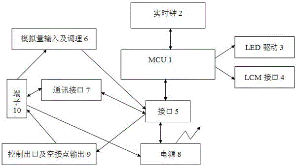
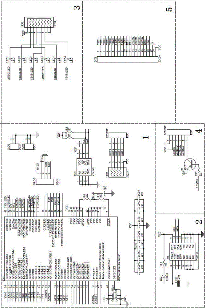
[0023] Such as Figure 2-6 As shown, the automatic device for on-line monitoring of the bus voltage transformer in the traction substation is characterized by: including MCU1, real-time clock 2, LED driver 3, LCM interface 4, two interfaces 5, analog input and conditioning 6, communication interface 7. Power supply 8, control outlet and empty contact output 9 and terminal 10, MCU1, real clock 2, LED driver 3, LCM interface 4 and an interface 5 constitute the main board, analog input and conditioning 6, communication interface 7, power supply 8, Control outlet and empty contact output 9, terminal 10 and another interface 5 form an input and output board; MCU1 uses a 16-bit single-chip microcomputer with data co-processing function as the CPU, and its built-in 12-bit AD converter is used to complete the data sampling function of the device , the CPU is connected to the clock chip and the data memory through the I2C bus; the real clock 2 adopts the clock chip integrated with the ...


PUM


Abstract

The invention provides a traction substation busbar potential transformer on-line monitoring automatic apparatus which is characterized by including an MCU, a real-time clock, an LED driver, an LCM interface, two interfaces, an analog input and conditioning unit, a communication interface, a power supply, a control outlet, a dead contact output unit, and a terminal. The MCU, the real-time clock, the LED driver, the LCM interface, and one interface form a main board, and the analog input and conditioning unit, the communication interface, the power supply, the control outlet, the dead contact output unit, and the terminal form an input and output board. The traction substation busbar potential transformer on-line monitoring automatic apparatus is advantageous in that the design is reasonable and the operation is reliable, the automatic, intelligent, time-interval-free switching and monitoring of YH can be realized, under the condition that the running YH has faults, data can be imported to another well-run YH timely and intelligently before the misoperation of a protection device, the voltage of the standby YH can be supervised and predicted and can be monitored in real time, and when the state or accessories have the trend to deteriorate, the early warning is timely sent to remind the attendant checking and processing.

Description

technical field [0001] The invention relates to an early warning, measurement and control device for a bus voltage transformer in a substation, in particular to an automatic online monitoring device for a bus voltage transformer in a traction substation. Background technique [0002] The voltage analog value of the 27.5kV (55kV) busbar voltage transformer in the traction substation is an indispensable and important data to realize the measurement and control of the traction substation. The misoperation of low-voltage start-up overcurrent protection and capacitor voltage loss protection on the high-voltage side and low-voltage side of the system will interrupt the power supply of catenary and equipment, and cause serious deviations in metering and measurement data. [0003] At present, the 27.5kV (55kV) bus on the low-voltage side of the main transformer in the traction substation generally adopts the single-bus wiring mode of the disconnector section, and a voltage transform...

Claims


Application Information

Patent Timeline
Patent Type & Authority Applications(China)
IPC IPC(8): G01R35/02
CPCG01R35/02
Inventor 李彦吉陈维华朱钰黄威斌陈崇海宋振泽王民杰林汪洋韩新春
Owner 李彦吉
Why Eureka
Try Eureka