
Heating furnace waste heat comprehensive utilization system and method

A heating furnace and waste heat technology, applied in lighting and heating equipment, chemical instruments and methods, furnaces, etc., can solve the problems of small steam flow, unsuitable use of steam turbines, large fluctuations, etc., and achieve low process cycle power consumption, The effect of significant social and economic benefits and low pretreatment requirements

Inactive Publication Date: 2016-10-26
BERIS ENG & RES CORP
View PDF9 Cites 11 Cited by
  • Summary
  • Abstract
  • Description
  • Claims
  • Application Information

AI Technical Summary

Problems solved by technology

High-temperature, high-pressure, large-flow, and stable steam is a high-quality heat source. Domestic steam turbine power generation technology is very mature, but the distribution of heating furnaces in iron and steel plants is scattered, and the quality of steam generated by vaporization and cooling of heating furnaces is low. The output of heating furnace fluctuates greatly, so it is not suitable to use steam turbine power generation technology
[0005] At the same time, the use of low-pressure steam generated by the vaporization cooling system of the heating furnace is restricted. The heating in winter causes serious depreciation of steam quality, and the large amount of steam released in summer causes huge waste.
In addition, the low-pressure steam generated by the heating furnace has a large heat loss during long-distance transportation
Similar problems are common in other industrial fields in my country. A large number of low-quality steam waste heat resources have not been efficiently utilized, which wastes energy and pollutes the environment.

Method used


Image

  • Heating furnace waste heat comprehensive utilization system and method
  • Heating furnace waste heat comprehensive utilization system and method

Examples


specific example

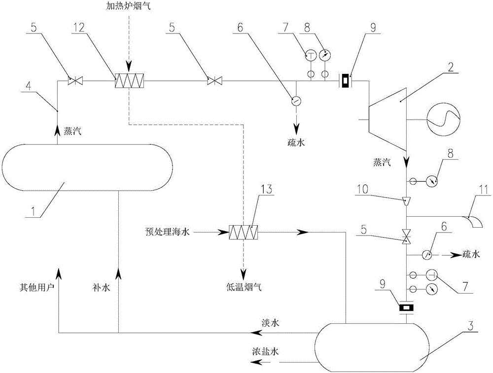
[0048] For a heating furnace with a rated output of 180t / h, the exhaust gas temperature at the furnace tail is about 700°C. An air heat exchanger is installed in the flue of the heating furnace. The flue gas passes through the air heat exchanger to preheat the combustion-supporting air. The temperature of the flue gas after the heat exchanger It is about 450°C. The rated saturated steam output of heating furnace vaporization cooling system 1 is 5.5t / h, and the steam pressure is 0.9MPa(G).

[0049] A steam superheater 12 is installed after the air heat exchanger, and the flue gas temperature after the steam superheater 12 is 2 , MgO, Al 2 o 3 and a small amount of Fe 2 o 3 , the pH value is greater than 7, it is weakly alkaline, the blast furnace slag flushing water has a large amount of water, and the pH value fluctuation range is small, and it is suitable for neutralization treatment with acidic concentrated brine.

[0050] The steam generated by the heating furnace vapor...


PUM


Abstract

The invention discloses a heating furnace waste heat comprehensive utilization system. The heating furnace waste heat comprehensive utilization system comprises a steam superheater, a power generator set and a sea water desalination device. The steam superheater is arranged in a heating furnace flue. Low pressure saturated steam generated by a heating furnace evaporated cooling system flows into the steam superheater and can be heated by heating furnace smoke to form superheated steam. The power generator set communicates with fluid of the steam superheater. The superheated steam generated in the steam superheater flows into the power generator set for power generation. The sea water desalination device communicated with fluid of the power generator set. The steam discharged by the power generator set flows into the sea water desalination device for sea water desalination. The invention further discloses a heating furnace waste heat comprehensive utilization method. Through the heating furnace waste heat comprehensive utilization system and method, gradient utilization of energy of the heating furnace steam is fully achieved, excessive pressure of the steam is used for power generation, and waste heat of the steam is further used for producing fresh water.

Description

technical field [0001] The invention relates to a comprehensive utilization system and method for waste heat of a heating furnace, belonging to the fields of waste heat utilization, seawater desalination and flue gas purification. Background technique [0002] The energy consumption of China's iron and steel industry accounts for about 16% of the country's total energy consumption, which is a high-energy-consuming industry. The energy consumption of the steel rolling process accounts for 10% to 20% of the total metallurgical energy consumption, and the energy consumption of the heating furnace accounts for about 65% to 80% of the steel rolling process. The heating furnace is the most important energy-consuming equipment in the steel rolling process. The rated unit consumption of the heating furnace is 1.1-1.5GJ / t, and the thermal efficiency of the heating furnace is generally 45%-60%. [0003] Among them, after the flue gas from the heating furnace passes through the air / ga...

Claims


Application Information

Patent Timeline
Patent Type & Authority Applications(China)
IPC IPC(8): F27D17/00C02F1/16F01C13/00C02F103/08
CPCC02F1/16C02F2103/08F01C13/00F27D17/004F27D17/008Y02A20/124Y02P10/25
Inventor 王惠永王伟宁李谦王振平
Owner BERIS ENG & RES CORP
Learn More