Composite airborne equipment stand for aircraft

A technology of composite materials and airborne equipment, which is applied to aircraft parts, transportation and packaging, and can solve problems such as reducing structural weight

Active Publication Date: 2017-12-29
哈尔滨新科锐复合材料制造有限公司 +1
View PDF7 Cites 0 Cited by
  • Summary
  • Abstract
  • Description
  • Claims
  • Application Information

AI Technical Summary

Problems solved by technology

[0003] The technical problem to be solved by the present invention is that during the design and development process of the aircraft airborne equipment stand, the original aluminum alloy structure stand has many parts, heavy weight, poor resistance to vibration shock and fatigue, and complex assembly process. Accurate control of airborne equipment is difficult. The existing airborne equipment platforms made of composite materials mainly have the disadvantages of not forming the overall structure and reinforcing ribs first and then gluing, resulting in increased glue consumption and weight gain; in order to overcome the existing Insufficient, it is possible to design a kind of composite material airborne equipment platform for aircraft, which adopts the overall co-cured structure of composite materials, reasonably designs the number of layers and direction of carbon fiber composite materials, and enhances the strength of the overall structure (the specific strength is higher than that of aluminum alloy 3 times), stiffness (specific stiffness is more than 2 times higher than that of aluminum alloy) and fatigue resistance (anti-fatigue life is more than 10 times higher than that of aluminum alloy), reducing the structural weight as much as possible

Method used


Image

  • Composite airborne equipment stand for aircraft
  • Composite airborne equipment stand for aircraft
  • Composite airborne equipment stand for aircraft

Examples


Embodiment Construction

[0013] The technical solution can also be realized through the following technical measures and the present invention will be further described below in conjunction with the accompanying drawings:

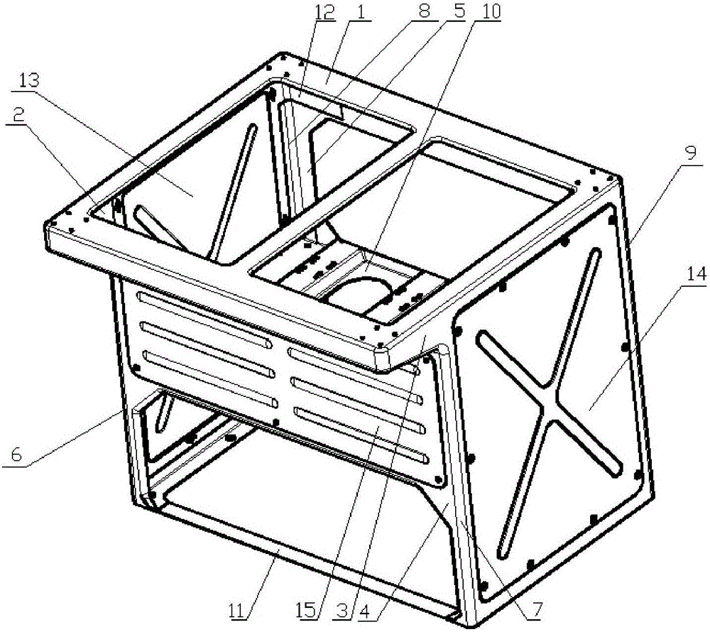
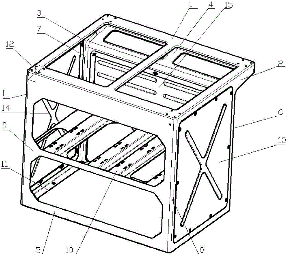
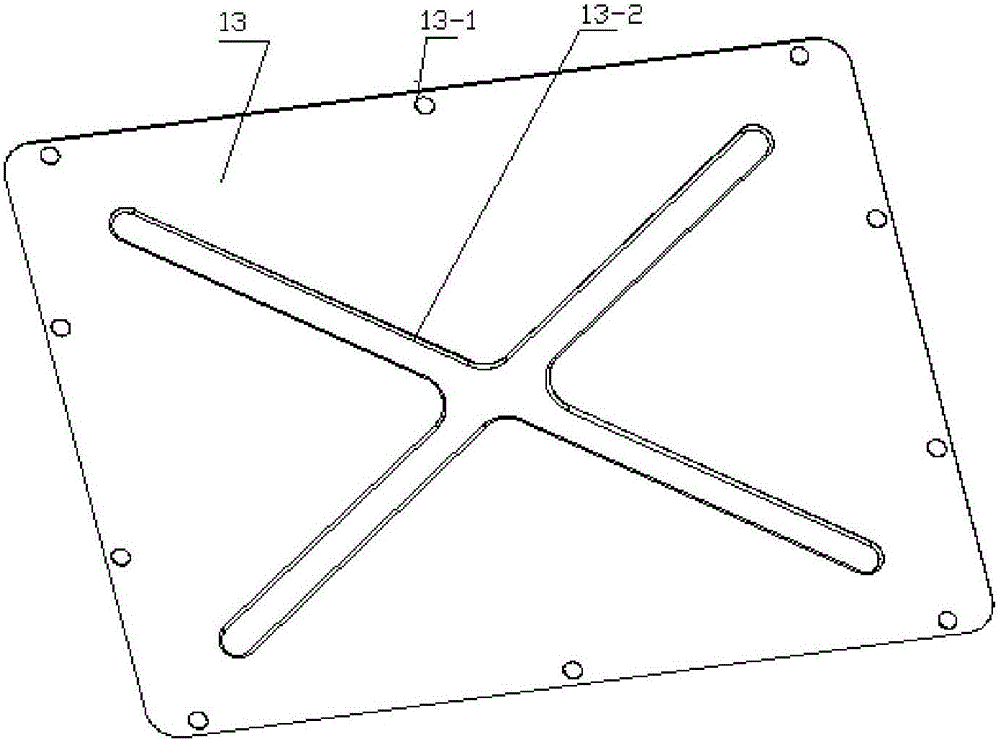
[0014] figure 1 It is a schematic diagram of the front three-dimensional structure of the present invention, figure 2 It is a schematic diagram of the three-dimensional structure of the back side of the present invention, a composite material airborne equipment stand for aircraft, consisting of an upper panel 1, a left wing panel 2, a right wing panel 3, a front panel 4, a rear panel 5, a left front support column 6, and a right front support column 7. The left rear support column 8, the right rear support column 9, the middle partition 10, the bottom plate 11, the corner reinforcement plate 12, the left maintenance opening cover 13, the right maintenance opening cover 14, and the front maintenance opening cover 15, It is characterized in that: the main frame structure of the com...


PUM

PropertyMeasurementUnit
thicknessaaaaaaaaaa

Abstract

The invention relates to a composite on-board device rack for an airplane. A traditional on-board device rack is formed by riveting aluminum alloy non-standard section bars and has the main defects of being large in number of parts, large in mass and poor in vibration resistance and fatigue resistance, and in order to overcome the defects and achieve an airplane part weight reduction purpose, a special composite on-board device rack used for installing and fixing operation and control instruments and meters and in-built instruments on the airplane. A multi-box hollow frame structure formed by a carbon fiber composite laying layer in an overall co-curing manner is mainly composed of an upper panel, a front panel, a rear panel, wing plates, supporting columns, a bottom plate, a middle partition, maintenance opening cover plates and the like, and the structure is formed through a die in a one-time heating and co-curing manner. The composite on-board device rack is small in structure mass, good in vibration resistance and fatigue resistance, small in number of parts and easy to assemble. The mass of the composite on-board device rack is smaller than that of the same aluminum alloy structure by about 30%, and the composite on-board device rack is suitable for being used for occasions such as the airplane with the weight reduction requirement.

Description

technical field [0001] The invention relates to a composite material airborne equipment stand for aircraft. Background technique [0002] At present, the airborne equipment stand for aircraft is an aircraft component. An important goal in the process of aircraft design and development is to minimize its weight under the premise of ensuring its use function and quality. The traditional airborne equipment stand is generally riveted by aluminum alloy non-standard profiles. The main disadvantages are: many parts, heavy weight, high production cost, easy deformation, poor corrosion resistance and oxidation resistance, vibration resistance, impact resistance and fatigue resistance. Poor, complex assembly process, complex equipment installation and maintenance, and short service life, resulting in shortened life of electrical components in the control platform, reduced control accuracy of airborne equipment, decreased payload of the whole machine, and decreased cruising range; exis...

Claims


Application Information

Patent Timeline
Patent Type & Authority Patents(China)
IPC IPC(8): B64D47/00B29C70/34
CPCB29C70/342B64D47/00
Inventor 扈心健匡永江曾艳王一双徐英杰林明张德生
Owner 哈尔滨新科锐复合材料制造有限公司
Why Eureka
Try Eureka