
Universal center-adjustment loading mechanism for upper disc

A loading mechanism and centering technology, which is applied in the directions of grinding machine tools, metal processing equipment, grinding devices, etc., can solve problems such as changes in processing efficiency, inability to guarantee the coincidence and parallelism of the two working surfaces, and impact, and achieves the flatness guarantee. Effect

Inactive Publication Date: 2016-10-26
SUZHOU HRT ELECTRONICS EQUIP TECH
View PDF5 Cites 0 Cited by
  • Summary
  • Abstract
  • Description
  • Claims
  • Application Information

AI Technical Summary

Problems solved by technology

[0002] The double-sided grinding and polishing equipment uses abrasive media to perform double-sided grinding on the surface of the workpiece through the reverse rotation of the upper and lower working surfaces around the center. In terms of pressure control, the traditional multi-stage pressure is used, and the pressure section is customized by the user. , but there is an impact when the pressure is switched, resulting in a sudden change in the force of the workpiece. On the other hand, due to the instability of the system pressure, the processing parameters (pressure, time, speed, and grinding liquid particle size, concentration, flow) Processing efficiency has changed
At the same time, this type of equipment has tended to be high-efficiency, high-precision or ultra-high-precision, and the fit of the upper and lower working surfaces of the equipment is very important to the quality of the processed products. If the two working surfaces are rigidly contacted and bonded directly, the two working surfaces The coincidence and parallelism of the surfaces cannot be guaranteed, and the workpiece is easily damaged and cracked when the two working surfaces are in contact. Therefore, it is necessary to adopt a structure with automatic centering, pressure buffering and pressure feedback complementary closed-loop control functions on the upper plate, so as to ensure that the two working surfaces The flexible contact of the two working surfaces achieves the purpose of precise control of the fit, parallelism and pressure of the two working surfaces

Method used


Image

  • Universal center-adjustment loading mechanism for upper disc
  • Universal center-adjustment loading mechanism for upper disc

Examples


Embodiment Construction

[0019] The present invention will be described in detail below with reference to the accompanying drawings and in combination with embodiments.

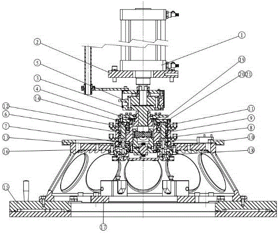
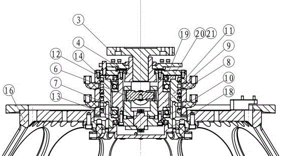
[0020] refer to figure 1 and figure 2 As shown, a universal self-aligning loading mechanism on the upper plate includes a master cylinder 1, the piston rod of the master cylinder 1 is respectively connected to the sensor 5 and the connecting shaft 3, and the connecting shaft 3 is connected to a joint 4 on the universal cross shaft. connected, the universal cross shaft upper joint 4 is provided with a universal joint 6 and a universal cross shaft lower joint 7, and the universal cross shaft upper joint 4 and the universal cross shaft lower joint 7 are respectively on the universal joint 6 The upper and lower ends are fixed and positioned, and the upper joint 4 of the universal cross shaft, the lower joint 7 of the universal cross shaft and the outside of the universal joint 6 are covered with a mandrel 8, and the upper and lower sid...


PUM


Abstract

The invention discloses a universal center-adjustment loading mechanism for an upper disc. The loading mechanism comprises a main air cylinder. A piston rod of the main air cylinder is connected with a sensor and a connecting shaft. The connecting shaft is connected with a universal cross shaft upper joint. A universal joint and a universal cross shaft lower joint are arranged below the universal cross shaft upper joint. A mandrel is arranged at the outer sides of the universal cross shaft upper joint, the universal cross shaft lower joint and the universal joint in a sleeving manner. An upper bearing is arranged at the upper side of the mandrel, and a lower bearing is arranged at the lower side of the mandrel. An outer supporting sleeve is connected to the outer sides of the upper bearing, the lower bearing and the mandrel in a sleeving manner. A swivel joint upper flange is arranged at the top ends of the mandrel, the outer supporting sleeve and a rotary connecting sleeve, and a water-cooling universal shaft assembly is formed. The lower end of the outer supporting sleeve is connected with the upper disc through an upper disc bracket. By means of the mechanism, the center can be adjusted automatically; the radial load or the axial load or the combined load existing in the radial direction and the axial direction at the same time can be borne, and thus center adjustment and stress of an upper disc system are guaranteed; and in addition, buffered unloading of the pressure inertia generated when the upper disc is combined with a lower disc can also be guaranteed.

Description

technical field [0001] The invention relates to the technical field of grinding machines or polishing machines, in particular to an upper plate universal self-aligning loading mechanism. Background technique [0002] The double-sided grinding and polishing equipment uses abrasive media to perform double-sided grinding on the surface of the workpiece through the reverse rotation of the upper and lower working surfaces around the center. In terms of pressure control, multi-stage pressure is traditionally used, and the pressure section is customized by the user. , but there is an impact when the pressure is switched, resulting in a sudden change in the force of the workpiece. Processing efficiency has changed. At the same time, this type of equipment has tended to be high-efficiency, high-precision or ultra-high-precision, and the fit of the upper and lower working surfaces of the equipment is very important to the quality of the processed products. If the two working surfaces...

Claims


Application Information

Patent Timeline
Patent Type & Authority Applications(China)
IPC IPC(8): B24B37/34B24B37/08
CPCB24B37/08B24B37/34
Inventor 乔卫民李方俊翟新马艳
Owner SUZHOU HRT ELECTRONICS EQUIP TECH
Learn More