
Double-layer vierendeel truss structure system of large cantilever structure

A technology of hollow truss and large cantilever, applied in truss-type structures, girders, trusses and other directions, can solve problems such as deformation, achieve the effect of convenient construction, meet the requirements of structural stress and deformation, and simple structure

Active Publication Date: 2012-03-21
广州市设计院集团有限公司
View PDF6 Cites 8 Cited by
  • Summary
  • Abstract
  • Description
  • Claims
  • Application Information

AI Technical Summary

Problems solved by technology

[0003] The purpose of the present invention is to solve the problems of force, deformation and vibration control in the prior art, and provide a double-layer vierendeel truss structure system with a large overhang structure. Under the condition of meeting the stress and deformation requirements of the building structure

Method used


Image

  • Double-layer vierendeel truss structure system of large cantilever structure
  • Double-layer vierendeel truss structure system of large cantilever structure
  • Double-layer vierendeel truss structure system of large cantilever structure

Examples


specific Embodiment 1

[0020] Figure 1 to Figure 5 Constitute the specific embodiment 1 of the present invention.

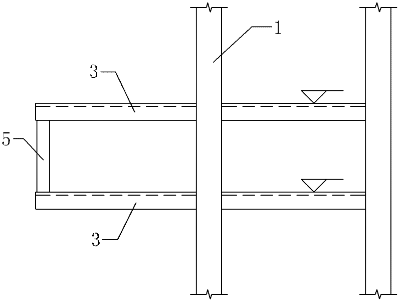
[0021] refer to Figure 1 to Figure 5 , the present embodiment includes a floor frame, and the floor frame is composed of frame columns 1, frame beams 2 and cantilever beams 3, and several main truss columns 4 are arranged between the upper and lower frame beams 2 of the floor, and through the The upper and lower frame beams 2 are connected with the main truss columns 4 to form a vierendeel truss structure on the first floor; several secondary truss columns 5 are arranged between the upper and lower cantilever beams 3 of the floor, and through the upper and lower suspension of the floor The cantilever beam 3 is connected with the main truss column 4 and the secondary truss column 5 to form a second-layer hollow truss structure; the double-layer hollow truss with a large cantilever structure is formed by the first-layer hollow truss structure and the second-floor hollow truss structur...

specific Embodiment 2

[0027] The feature of this embodiment is: the frame beam 2 can be extended by at least one span to form an extension section (not shown in the accompanying drawings). There may be a rigid connection between the cantilever beam 3 and the extension section. All the other can be with specific embodiment 1.

[0028] In each embodiment of the present invention, the quantity of the main truss columns 4 between the upper and lower frame beams 2 of the floor can be determined according to the overall requirements of the architectural design, and can be two, three, five, six, seven, eight, Nine, ten, twelve, fifteen, seventeen, nineteen or more than twenty; corresponding to the number of main truss columns 4, the secondary truss columns between the upper and lower cantilever beams 3 of the floor The number of 5 can be determined according to the overall requirements of the architectural design, which can be two, three, five, six, seven, eight, nine, ten, twelve, fifteen, seventeen, ni...


PUM


Abstract

The invention discloses a double-layer vierendeel truss structure system of a large cantilever structure, comprising a floor frame. The floor frame comprises frame columns (1), frame beams (2) and cantilever beams (3). The double-layer vierendeel truss structure system of the large cantilever structure is characterized in that a plurality of main truss columns (4) are arranged between the upper and lower frame beams (2) of the floor, the upper and lower frame beams (2) of the floor are connected with the main truss columns (4) to form a first-layer vierendeel truss structure, a plurality of auxiliary truss columns (5) are arranged between the upper and lower cantilever beams (3) of the floor, the upper and lower cantilever beams (3) of the floor are connected with the auxiliary truss columns (5) to form a second-layer vierendeel truss structure, and the first-layer vierendeel truss structure and the second-layer vierendeel truss structure are connected to form the double-layer vierendeel truss structure system of the large cantilever structure. The double-layer vierendeel truss structure system of the large cantilever structure has a simple structure and is convenient to construct. A space frame structure system is formed by two layers of vierendeel trusses. The double-layer vierendeel truss structure system of the large cantilever structure can meet the structure stress and deformation requirement under the condition of adopting the small beams.

Description

technical field [0001] The invention relates to a truss structure system, in particular to a double-layer vierendeel truss structure system with a large overhang structure. It belongs to the field of building structure. Background technique [0002] In modern buildings, with the continuous development of construction technology, a large number of large cantilevered building structures have appeared in modern buildings. While the length of the cantilever increases, the bending moment borne by the cantilever beam is in accordance with the square relationship of the cantilever length And the rapid increase, the resulting deflection deformation increases rapidly with the cubic relationship of the length of the cantilever, and the vibration control of the cantilever section has become the main problem at present. cannot be increased accordingly. Therefore, the stress, deformation and vibration control of the large overhanging building structure are the problems to be solved by ...

Claims


Application Information

Patent Timeline
Patent Type & Authority Applications(China)
IPC IPC(8): E04B1/19E04C3/02E04B1/58
Inventor 王一功韩建强罗沁
Owner 广州市设计院集团有限公司
Learn More