Flue gas purifying system

A flue gas purification system and flue gas purification technology are applied in the direction of gas treatment, chemical instruments and methods, combined devices, etc., which can solve the problems of inconvenient recovery by semi-comprehensive methods, fast pollution of excreta, and low recycling efficiency. Achieve the effect of saving installation time, small equipment size and saving floor space

Active Publication Date: 2016-10-26
北京凯元环保技术有限公司
View PDF3 Cites 3 Cited by
  • Summary
  • Abstract
  • Description
  • Claims
  • Application Information

AI Technical Summary

Problems solved by technology

[0007] 1. Dust removal: according to the efficiency of dust removal, there are: ceramic filter dust removal, high-voltage electrostatic bag dust removal, water film dust removal, but the recycling efficiency is low, the cost of dust removal equipment is high, and the actual dust removal efficiency does not exceed 90%.
[0008] 2. Desulfurization: There are dry desulfurization (recovering elemental sulfur) and wet desulfurization (alkaline desulfurization, recovering sulfate), but the average recovery rate is low, the cost of desulfurization equipment and additives is high, and the actual desulfurization efficiency does not exceed 80%.
This semi-comprehensive treatment method can reduce a small amount of investment, but the improvement of flue gas purification is not obvious, and the semi-comprehensive method is inconvenient and uneconomical for recycling
However, if the waste gas treated by the semi-comprehensive method is directly discharged outside, the excrement pollution rate is faster, and the secondary pollution caused is still very serious.

Method used


Image

  • Flue gas purifying system
  • Flue gas purifying system
  • Flue gas purifying system

Examples


Embodiment 1

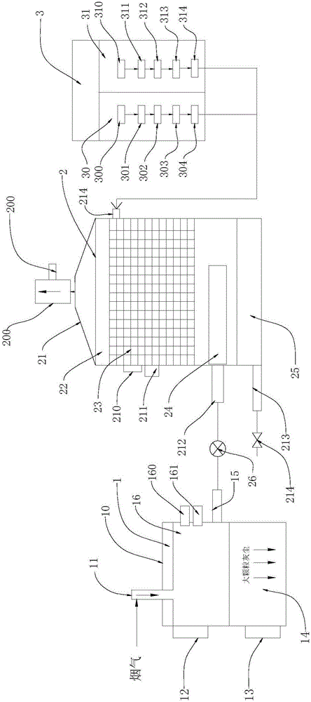
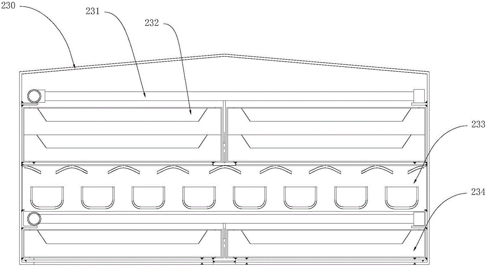
[0035] see figure 1 and image 3 , The flue gas purification system of this embodiment includes a cold and heat exchange unit 1 for flue gas cooling, a flue gas purification unit 2, and a chemical dosing unit 3 for adding additives and reactants to the flue gas purification unit 2 .

[0036] The cold heat exchange unit 1 includes a cold heat exchange unit housing 10 and a gravity dust removal box 14 and a cold heat exchanger 16 located inside the cold heat exchange unit housing 10, and the cold heat exchanger 16 is located between the gravity dust removal box 14 Above, an air inlet 11 is provided on the upper part of the cooling and heat exchange unit housing 10 , and a thermometer 12 , a liquid level gauge 13 and an air outlet 15 are provided on the side of the cooling and heat exchanging unit housing 10 . The cold heat exchanger 16 is provided with a water inlet 161 and a water outlet 160, the water inlet 161 communicates with an external cold water source pipeline, and th...

Embodiment 2

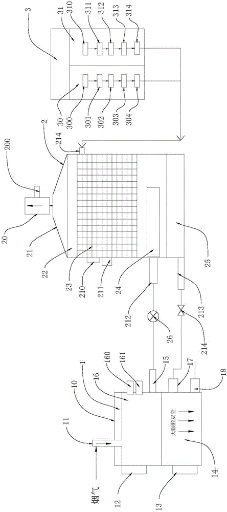
[0048] see figure 2 and image 3 , on the basis of Embodiment 1, a mixed liquid dust removal inlet 17 and a mixed liquid dust removal outlet 18 communicating with the gravity dust removal box 14 are added to the side wall of the cold and heat exchange unit housing 10, and the outlet of the valve 214 is connected to the mixed liquid dust removal inlet 17 . In this way, during the flue gas purification process, the mixed liquid enters the gravity dust removal box 14 through the mixed liquid dust removal inlet 17 , and is discharged from the mixed liquid dust removal outlet 18 after washing the gravity dust removal box 14 .

[0049] Compared with Embodiment 1, this embodiment adds a channel for the mixed liquid to flush the gravity dust removal box 14, which can realize the online scrubbing and cleaning of the gravity dust removal box 14, saves the workload of manual cleaning, and improves the whole flue gas treatment at the same time. system work efficiency.

[0050] Similar...


PUM


Abstract

The invention discloses a flue gas purifying system, comprising a heat-cold exchange unit used for cooling flue gas, a flue gas purifying unit and a chemical adding unit used for adding auxiliary agents and reactants into the flue gas purifying unit, wherein the flue gas purifying unit is of a tower shape and comprises a reactor shell; a mixed liquid chamber, a gas chamber, a filtering and treating unit and a demister are arranged in the reactor shell from bottom to top; a gas outlet is formed in the top of the reactor shell; the side wall of the reactor shell is provided with an exhaust gas inlet communicated with the gas chamber, a mixed liquid outlet communicated with the mixed liquid chamber, a spraying liquid inlet communicated with the filtering and treating unit, a temperature controller and a liquid level controller; the exhaust gas inlet is connected with a fan through a pipeline; the fan is communicated with the heat-cold exchange unit through a pipeline; the mixed liquid outlet is provided with a valve; and the spraying liquid inlet is connected with the chemical adding unit through a pipeline and communicated with an external water supply pipeline.

Description

technical field [0001] The invention relates to the field of environmental protection, in particular to a flue gas purification system. Background technique [0002] Industrial civilization and urban development, while creating huge wealth for human beings, also discharge billions of tons of exhaust gas and waste into the atmosphere. The atmosphere on which human beings depend for survival has become a repository of garbage and poisonous gas in the sky. When the harmful gases and pollutants in the atmosphere reach a certain concentration, it will bring huge disasters to human beings and the environment. Air pollution has become an inescapable reality in the lives of urban residents all over the world. The industrial waste gas produced by coal-fired and oil-fired equipment is an important source of air pollution. [0003] As of the end of 2006, the unit capacity of desulfurization equipment installed in my country's coal-fired power stations alone reached 150 million kilowat...

Claims


Application Information

Patent Timeline
Patent Type & Authority Applications(China)
IPC IPC(8): B01D50/00B01D53/75B01D53/78B01D53/86B01D53/60B01D53/64
CPCB01D53/60B01D53/64B01D53/75B01D53/78B01D53/8637B01D53/8665B01D2255/40B01D2258/0283B01D50/10
Inventor 王涛
Owner 北京凯元环保技术有限公司
Why Eureka
Try Eureka