Chip breaking drill bit with step edge type

A step and drill technology, which is applied in step drilling, drill repairing, tool manufacturing, etc., can solve the problems that affect the processing efficiency and quality, the chip cannot be discharged smoothly in time, the tool is worn and damaged, etc., so as to facilitate the smooth discharge and ensure the workpiece Effect of machining surface quality and reducing contact area

Inactive Publication Date: 2016-10-12
SHANDONG UNIV
View PDF6 Cites 5 Cited by
  • Summary
  • Abstract
  • Description
  • Claims
  • Application Information

AI Technical Summary

Problems solved by technology

Especially when drilling difficult-to-machine materials, because it is a semi-closed process, limited by the space of the drill groove, the chips cannot be discharged smoothly in time, which is likely to cause chip blocking and entanglement, aggravate tool wear and damage, and seriously affect the processing efficiency and machining efficiency. quality

Method used


Image

  • Chip breaking drill bit with step edge type
  • Chip breaking drill bit with step edge type
  • Chip breaking drill bit with step edge type

Examples


Embodiment Construction

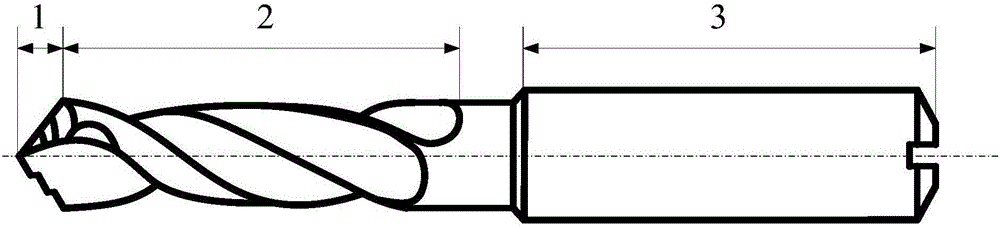
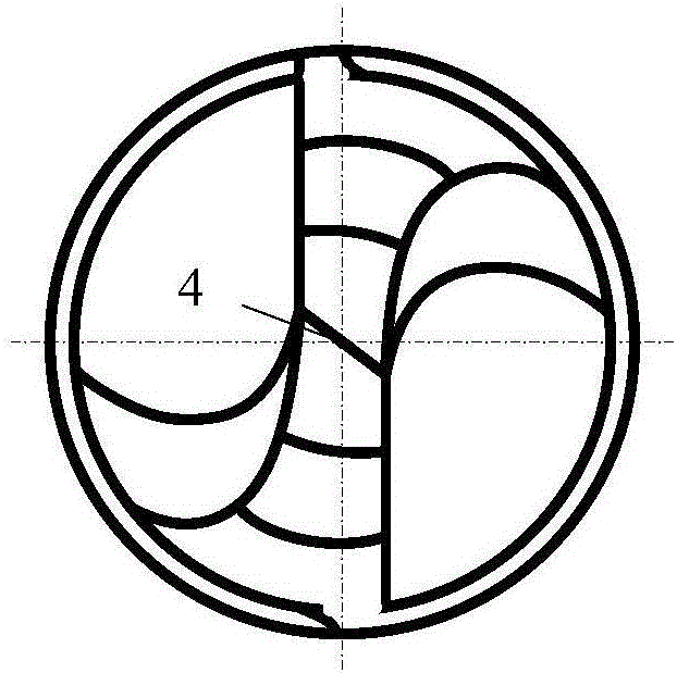
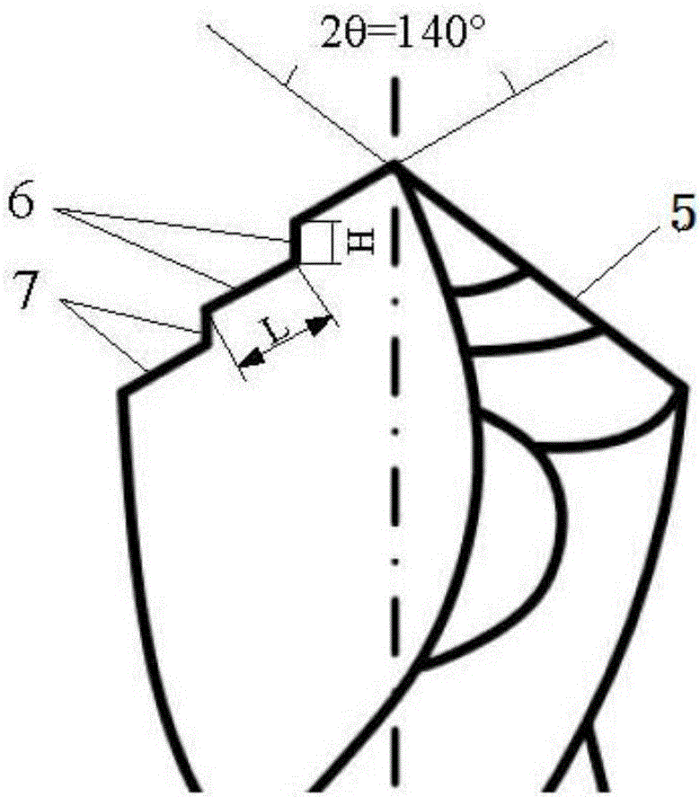
[0018] The chip breaking drill bit with stepped edge type of the present invention is made of cemented carbide, such as figure 1 , figure 2 and image 3 As shown, it mainly includes a drill tip 1 , a guide part 2 and a tool handle 3 , and the guide part 2 is arranged between the drill tip 1 and the tool handle 3 . The drill tip 1 includes a chisel edge 4 and two main cutting edges 5 . In order to adapt to the drilling of difficult-to-machine materials, the apex angle 2θ of the drill point is 140°, which reduces the load on the unit cutting edge and reduces tool wear. The helix angle of the guide part 2 is 40° to increase the space of the chip flute, avoid chip clogging and ensure the smooth discharge of chips.

[0019] The chisel edge 4 is located at the center of the drill point between the two main cutting edges 5. During the drilling process, a large torque will be generated due to the resistance of the material. In order to ensure the rigidity and strength of the drill...


PUM


Abstract

A chip breaking drill bit with a step edge type comprises a drill tip, a guide part and a tool handle. The guide part is arranged between the drill tip and the tool handle. The drill tip comprises a chisel edge and two main cutting edges. The chisel edge is located between the two main cutting edges. Each main cutting edge comprises a front tool face and a rear tool face. Each main cutting edge is in a step edge type and comprises a first step edge body and a second step edge body, both of which are composed of a step transverse edge body and a step vertical edge body. According to the drill bit, step structure design is conducted on the main cutting edges, so that the load on unit cutting edge is reduced, the contact area of the rear tool faces of a tool and the machined surface of a workpiece is reduced, and the cutting force is reduced; meanwhile, through the step edge type, the deformation degree of cutting chips can be effectively increased, the cutting chips can be easily broken, smoothly discharged and prevented from twining around the tool, the quality of the machined surface of the workpiece and the service life of the tool are guaranteed, the durability of the tool is improved, and the machining quality and the machining efficiency are guaranteed.

Description

technical field [0001] The invention relates to a chip-breaking drill suitable for drilling difficult-to-machine materials, and belongs to the technical field of drilling tools in mechanical processing. Background technique [0002] In modern industry, especially in aerospace, petrochemical, medical equipment and other fields, with the rapid development of science and technology, the requirements for the performance of the applied materials are getting higher and higher, and they need to have high strength and hardness, good heat resistance , Wear resistance and corrosion resistance, due to the physical and mechanical properties of these materials, determine their difficulty in processing, and are collectively referred to as "difficult to process materials", such as high-strength steel, high-temperature alloys, titanium alloys, and composite materials. Especially when drilling difficult-to-machine materials, because it is a semi-closed process, limited by the space of the dr...

Claims


Application Information

Patent Timeline
Patent Type & Authority Applications(China)
IPC IPC(8): B23B51/00
CPCB23B51/009B23B2251/14B23B2251/18B23B2251/48B23B2251/60
Inventor 孙杰朱兆聚国凯刘凯
Owner SHANDONG UNIV
Why Eureka
Try Eureka