A near-net additive manufacturing method for electron beam fuses

A manufacturing method and electron beam technology, applied in the field of additive manufacturing, can solve problems such as the inability to balance the forming surface quality and forming efficiency, the inability to realize near-net additive manufacturing of metal materials, and the rough surface of the stacked layer, so as to improve the aesthetics, The effect of accurate external dimensions and small machining allowance

Active Publication Date: 2018-11-09
XIAN ZHIRONG METAL PRINTING SYST CO LTD
View PDF6 Cites 0 Cited by
  • Summary
  • Abstract
  • Description
  • Claims
  • Application Information

AI Technical Summary

Problems solved by technology

If a thinner welding wire is used, the size of the formed molten pool is small, and the surface quality of the deposited layer is good, but the forming efficiency is indeed very low.
If a thicker welding wire is used, the efficiency of melting and forming accumulation is very high, but the surface of the formed accumulation layer is rough and the appearance is poor. Usually, more machining allowance is required to ensure the effective size of the workpiece
In short, the use of ordinary fuse rapid prototyping equipment cannot take into account the two factors of forming surface quality and forming efficiency, and it is impossible to achieve near-net additive manufacturing of metal materials

Method used


Image

  • A near-net additive manufacturing method for electron beam fuses
  • A near-net additive manufacturing method for electron beam fuses
  • A near-net additive manufacturing method for electron beam fuses

Examples


Embodiment Construction

[0021] The present invention will be described in more detail below in conjunction with the accompanying drawings and embodiments.

[0022] First of all, it should be explained that the words "thick" and "thin" mentioned in this embodiment are relative concepts, rather than a certain specific size. These words are used only to illustrate the technical solution of the present invention more clearly and clearly. , and are not intended to limit the protection scope of the present invention.

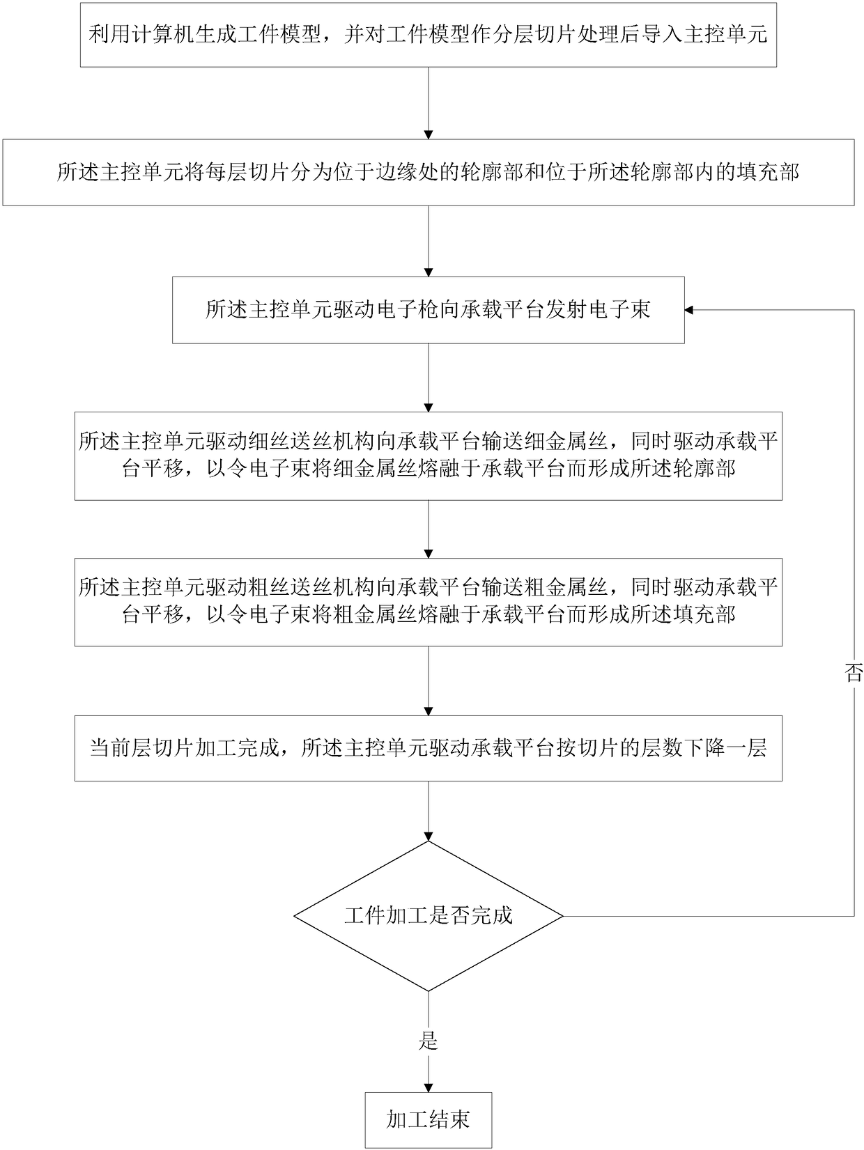
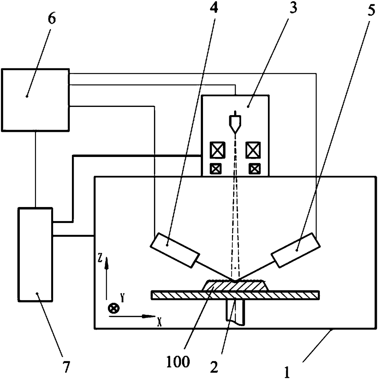
[0023] The invention discloses a near-net additive manufacturing method for an electron beam fuse, which combines Figure 1 to Figure 3 As shown, the method is realized based on a device, and the device includes a vacuum chamber 1, a carrying platform 2, an electron gun 3, a thin wire feeding mechanism 4, a thick wire feeding mechanism 5 and a main control unit 6, Described method comprises the following steps:

[0024] Step S1, using a computer to generate a workpiece model, and importing...


PUM


Abstract

The invention discloses a method for near-net additive manufacturing of electron beam fuses. The method includes: using a computer to generate a workpiece model, and layering and slicing the workpiece model and then importing it into a main control unit; the main control unit converts each Layer slicing is divided into outline part and filling part; the main control unit drives the wire feeding mechanism to deliver thin metal wires to the carrying platform, and at the same time drives the carrying platform to translate, and uses electron beams to melt the thin metal wires on the carrying platform to form the Outline part; the main control unit drives the thick wire feeding mechanism to feed the thick metal wire to the carrying platform, and at the same time drives the carrying platform to translate, and uses the electron beam to melt the thick metal wire on the carrying platform to form the filling part; repeat the above steps, Until the multi-layer slices are piled up to form a workpiece. The invention can improve the processing efficiency and appearance quality of the workpiece, so that after the workpiece is formed, it has a small processing allowance and accurate external dimensions.

Description

technical field [0001] The invention relates to the technical field of additive manufacturing, in particular to a method for near-net additive manufacturing of electron beam fuses. Background technique [0002] Additive manufacturing technology is also known as 3D printing or rapid prototyping technology. It is a technology based on digital three-dimensional model drawing files, using materials such as metal powder, wire or bondable plastic, to construct objects by stacking and accumulating layer by layer. Rapid prototyping manufacturing technology is widely used in mold manufacturing, industrial design and other fields, and is gradually being used in the direct manufacturing of some products, especially some high-value applications, such as hip joints or teeth and some aircraft parts. [0003] Metal parts rapid prototyping manufacturing methods mainly include laser selective sintering (SLS), laser selective melting (SLM), laser coaxial powder feeding direct manufacturing, ...

Claims


Application Information

Patent Timeline
Patent Type & Authority Patents(China)
IPC IPC(8): B22F3/105B33Y10/00B33Y30/00
CPCB33Y10/00B33Y30/00B22F10/00B22F12/222B22F12/70B22F12/224B22F10/25B22F10/366Y02P10/25
Inventor 郭光耀
Owner XIAN ZHIRONG METAL PRINTING SYST CO LTD
Why Eureka
Try Eureka