Self-powered oil and gas pipeline monitoring device

A technology for oil and gas pipelines and monitoring devices, applied in electrical components, pipeline systems, generators/motors, etc., can solve the problems of electromagnetic interference, unsuitable pipelines, and high cost of power generation devices, and achieve uniform stress distribution, controllable deformation, and diameter. small-scale effect

Active Publication Date: 2016-09-21
山东亿维新材料有限责任公司
View PDF8 Cites 5 Cited by
  • Summary
  • Abstract
  • Description
  • Claims
  • Application Information

AI Technical Summary

Problems solved by technology

Although some of the pipeline leakage or anti-theft monitoring and alarm methods proposed are relatively mature at the technical level, the application of the anti-theft monitoring system for long-distance pipelines in China is still in the preliminary stage and has not been widely used. One of the main reasons is that The power supply problem of the monitoring system has not been well resolved: 1) The method of laying cables is expensive and is easily cut off by criminals, which affects the normal operation of the monitoring system; 2) When using batteries for power supply, the use time is limited and needs to be replaced frequently. Once the battery is insufficient and not replaced in time, the remote transmission of monitoring information cannot be completed; 3) In recent years, in order to meet the self-power supply requirements of related wireless sensor monitoring systems, people have also proposed various forms of turbine-type miniature power generation devices. The biggest problem is that the structure is complex and the volume is relatively large, which is not suitable for occasions with small diameter pipes. Some structures of power generation devices also have electromagnetic interference and other phenomena, and their popularization and application have been restricted to a certain extent.

Method used


Image

  • Self-powered oil and gas pipeline monitoring device
  • Self-powered oil and gas pipeline monitoring device
  • Self-powered oil and gas pipeline monitoring device

Examples


Embodiment Construction

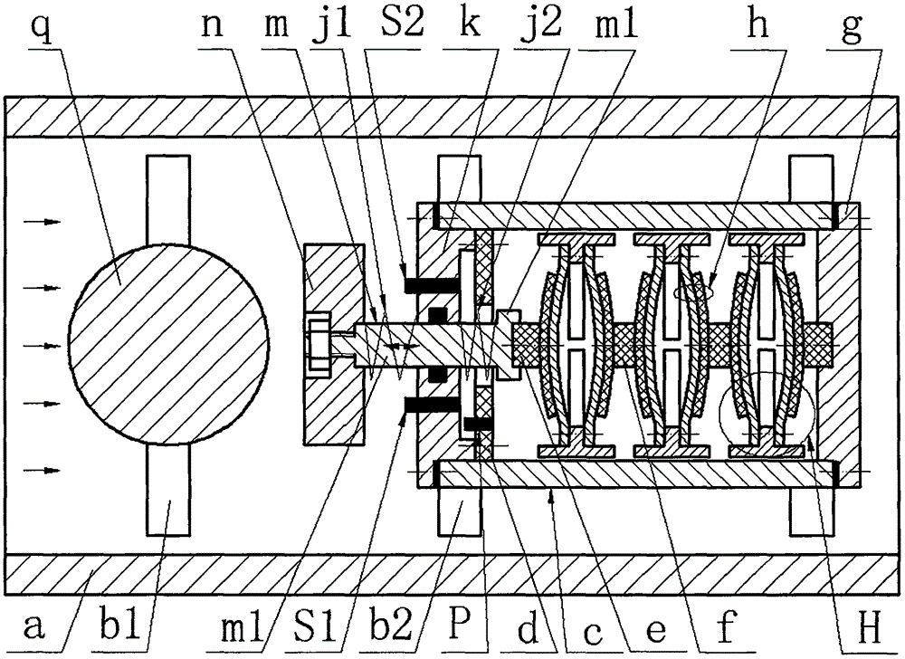
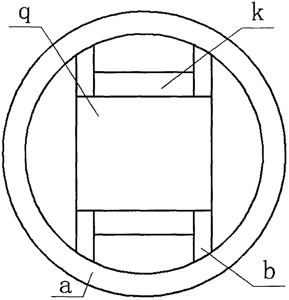
[0014] On the inner wall of the pipe a, a cylindrical spoiler q is installed through the first rib b1, and an inner cylinder c is installed through the second rib b2. The center of the spoiler q is perpendicular to the center of the inner cylinder c, and the left and right ends of the inner cylinder c The left end cover k and the right end cover g are respectively installed with screws; the temperature sensor S1 and the pressure sensor S2 are inlaid on the left end cover k, and the side of the left end cover k close to the inner cylinder c is installed with a circuit board d with a transmitting unit P through screws. The left semi-axis m1 of the stepped shaft m protrudes from the inner cylinder c through the center hole of the left end cover k, and the end of the left semi-axis m1 is equipped with an actuator n; the left semi-axis m1 is covered with a balance spring j1 and a limit spring j2 , the left and right ends of the balance spring j1 lean against the exciter n and the le...


PUM


Abstract

The invention relates to a self-powered oil and gas pipeline monitoring device and belongs to the field of fluid monitoring. A turbulator and an inner barrel are mounted on the inner wall of a pipeline through a rib plate I and a rib plate II, and end covers are mounted at two ends of the inner barrel; a temperature sensor and a pressure sensor are embedded onto the left end cover, and a circuit board is mounted on the left end cover; the left half shaft of a stepped shaft extends out from the left end cover and an exciter is mounted on the end part, and a balance spring and a limit spring sleeve the left haft shaft; two piezoelectric vibrators formed by splicing by metal base plates and piezoelectric wafers and an n-shaped framework mounted on the end parts of the piezoelectric vibrators form a transducer; piezoelectric vibrators on the left and right sides in the inner barrel are connected to buffer cushions on the right half shaft and the right end cover, respectively, and adjacent piezoelectric vibrators on two different transducers are connected through an isolation pad. The device provided by the invention has the advantages that power generation and flow velocity self-measurement are realized by virtue of a fluid-solid coupling effect, so that true flow velocity online monitoring can be realized; a monitor is arranged along the length direction of the pipeline, so that the device is simple in structure and small in radial dimension and easily obtain required energy through multiple piezoelectric vibrators; and the piezoelectric vibrators are reasonable in structure, large in generating capacity and high in reliability.

Description

technical field [0001] The invention belongs to the technical field of pipeline fluid monitoring, and in particular relates to a self-powered oil and gas pipeline monitoring device. Background technique [0002] Due to natural corrosion, natural force majeure, and man-made theft, leakage events of long-distance pipelines for oil and natural gas and other fluids during use occur from time to time. Frequent pipeline leakage not only causes huge economic losses, but also affects the surrounding nature. The environment has caused serious pollution. In the past, regular manual inspections were often used for maintenance. However, due to the long laying distance of oil and gas pipelines and the fact that they are often located in inaccessible or inconvenient places, regular inspections are difficult to find leaks and maintain them in time. Therefore, various types have been proposed for pipeline leakage monitoring or anti-theft systems. Although some of the pipeline leakage or a...

Claims


Application Information

Patent Timeline
IPC IPC(8): F17D5/06F03B13/00H02N2/18
CPCF03B13/00F17D5/06H02N2/185
Inventor 阚君武富佳伟曾平王淑云李新辉
Owner 山东亿维新材料有限责任公司
Why Eureka
Try Eureka