T-shaped steel member

A technology of T-shaped steel and steel components, which is applied to building components, elongated structural components for load-bearing, structural elements, etc. The effect of bearing capacity, reducing steel consumption and improving component performance

Inactive Publication Date: 2016-09-21
初明进
View PDF4 Cites 2 Cited by
  • Summary
  • Abstract
  • Description
  • Claims
  • Application Information

AI Technical Summary

Problems solved by technology

[0004] In order to solve the problems of large amount of steel used in existing steel components, heavy welding...

Method used


Image

  • T-shaped steel member
  • T-shaped steel member
  • T-shaped steel member

Examples


Embodiment Construction

[0035] The T-shaped steel member of the present invention will be described in detail below with reference to the drawings and embodiments.

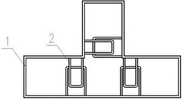
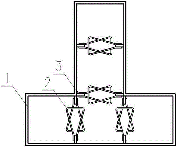
[0036] A schematic cross-sectional view of an embodiment of the T-shaped steel member proposed by the present invention, as figure 1 , the T-shaped steel member includes a T-shaped steel part 1 and a connecting part 2, and the opposite connecting parts 2 are overlapped together; the connecting parts are arranged at a certain interval along the longitudinal direction of the steel part, figure 1 Among them is a section of the steel part and the arrangement of the connecting parts; the connecting parts are made of steel rods, or the connecting parts are made of deformed steel bars, or made of steel strips; figure 1 The connector 2 is U-shaped. figure 1 The widths of the U-shaped connectors on the opposite side are the same, and for the convenience of expression, the widths of the U-shaped connectors on the opposite sides are differentiated...


PUM


Abstract

The invention relates to a T-shaped steel member, and belongs to the technical field of steel structures. The steel member comprises a T-shaped steel part of which the outer contour is shaped like T and connectors, the connectors are connected to steel part long edge steel plates, and the connectors on the opposite sides are connected in a lapped mode. According to the T-shaped steel member, the stress performance of the structure and an industrialization level are improved.

Description

technical field [0001] The invention relates to a T-shaped steel component. Background technique [0002] The steel structure has a high degree of industrialization and good mechanical performance, and it is more and more widely used in building structures. The shear wall has high bearing capacity and high lateral stiffness, and is the main lateral force-resistant structural component of high-rise structures. [0003] Composite members such as concrete-filled steel tube columns are generally square or circular in cross-section, giving full play to the confinement effect of steel tubes. The steel-concrete composite shear wall has the performance advantages of the shear wall, and also has the advantages of the manufacture and installation of the steel structure; the ratio of the long side to the short side of the section of the steel-concrete composite shear wall is greater than 1, and the restraining effect of the steel is reduced. Generally, the components are separated by...

Claims


Application Information

Patent Timeline
IPC IPC(8): E04C3/00E04C3/06E04C3/32E04C3/293
CPCE04C3/00E04C3/06E04C3/293E04C3/32E04C3/34E04C2003/0413E04C2003/046
Inventor 初明进
Owner 初明进
Why Eureka
Try Eureka