Eureka AIR delivers breakthrough ideas for toughest innovation challenges, trusted by R&D personnel around the world.

Polishing abrasive particle, production method therefor, polishing method, polishing device, and slurry

A technology of abrasive grains and slurry, which is applied in the direction of grinding equipment, grinding machine tools, manufacturing tools, etc., and can solve the problem that diamond abrasive grains cannot be reused

Active Publication Date: 2016-09-14
ASAHI CHEM IND CO LTD
View PDF10 Cites 11 Cited by
  • Summary
  • Abstract
  • Description
  • Claims
  • Application Information

AI Technical Summary

Problems solved by technology

As a result, there is a problem that expensive diamond abrasive grains cannot be reused

Method used


Image

  • Polishing abrasive particle, production method therefor, polishing method, polishing device, and slurry
  • Polishing abrasive particle, production method therefor, polishing method, polishing device, and slurry
  • Polishing abrasive particle, production method therefor, polishing method, polishing device, and slurry

Examples


Embodiment 1

[0194] [Structure and function of abrasive grains for grinding]

[0195] Figure 4 A and Figure 4 B is a micrograph of the abrasive grains for grinding of the present invention, Figure 4 A The following is an explanatory diagram of its grinding effect.

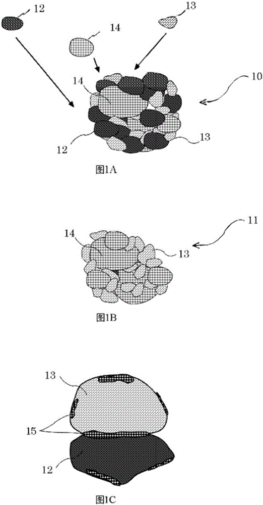
[0196] Figure 4 A is a micrograph showing the polishing abrasive grains of Example 1. FIG. Since the latter has just been integrated, abrasive grains of various sizes are mixed. Those with an average particle size of 5 to 6 μm and a particle size of about 1 μm are mixed. Figure 4 B is an enlarged view of its part. This is a photograph of one abrasive grain with an outer diameter of approximately 6 μm. Three types of components that have been pulverized in advance are mixed and strongly connected to each other. The three types of components are all integrated into particles while maintaining their inherent physical and chemical properties. The abrasive grains for polishing of the examples are integrated with such a...

Embodiment 2

[0217] [Verify the effect of the first component]

[0218] Figure 7 It is a comparative graph of the polishing rate when polishing SiC with the first component replaced.

[0219] The portion denoted Sample 1-1 shows the use of Al in the grinding of SiC 2 o 3 with MnO 2 and CaCO 3 The result of integrated abrasive grains for grinding.

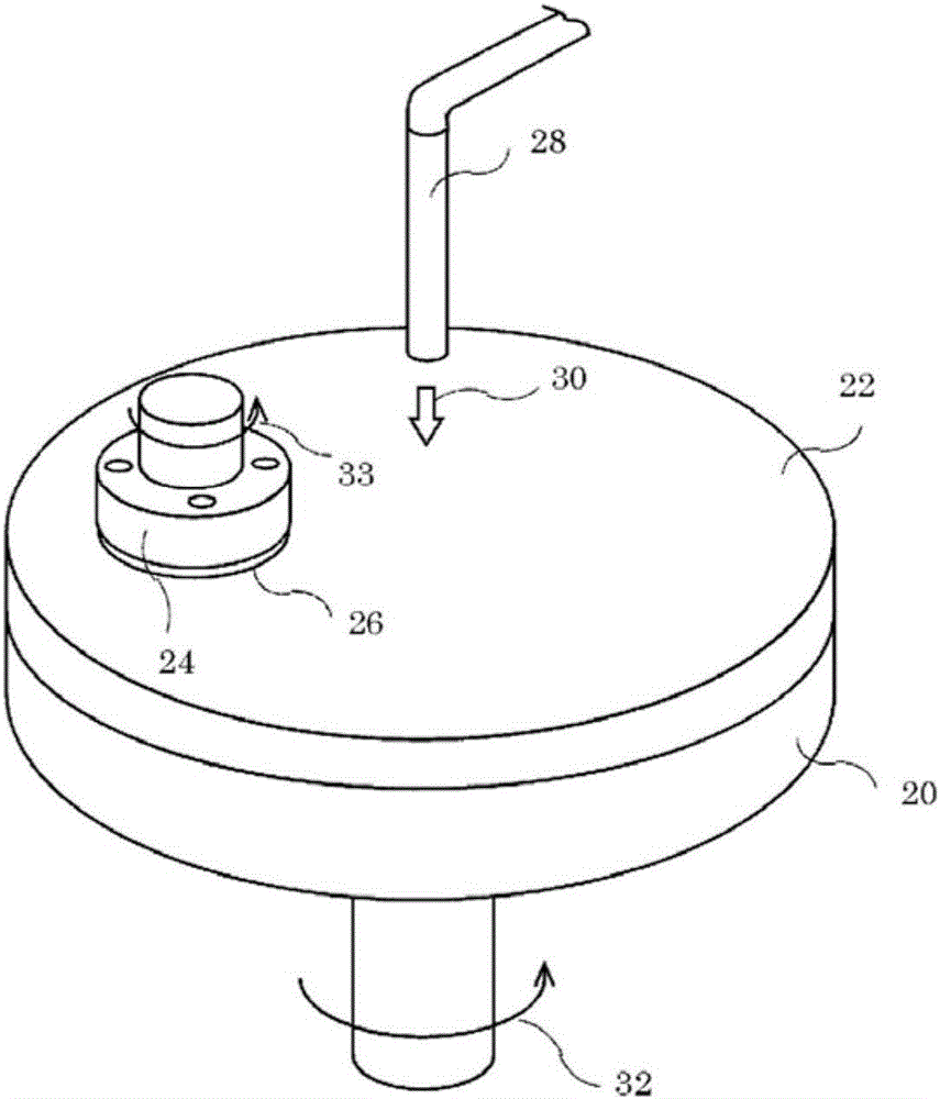
[0220] In this embodiment, the operating conditions of the grinding device are that the number of revolutions of the grinding platen 20 is set at 50 revolutions per minute (rpm), the number of revolutions of the holding device 24 is set at 100 revolutions per minute, and the holding device 24 moves the material to be ground 26 toward The grinding pressure pressed in the direction of the grinding platen 20 is set as 160 grams (g / cm2) per 1 square centimeter. 2 ). The abrasive grains for polishing were mixed in pure water in an amount of 15% by weight. The thus adjusted slurry was supplied onto the polishing pad 22 from the liquid injecto...


PUM

PropertyMeasurementUnit
particle diameteraaaaaaaaaa
roughnessaaaaaaaaaa
particle diameteraaaaaaaaaa

Abstract

[Problem] To polish the surface of an object material at a high removal rate and into a high-quality surface. [Solution] The object material is polished by wet polishing. A slurry comprises polishing abrasive particles dispersed in pure water. Each of the polishing abrasive particles comprises a component that exerts a mechanochemical action, a component that reacts to a frictional heat generated when polishing the object material, and the like, integrated into a particle as a whole. The components are bonded directly to one another by mechanical alloying while each retains the inherent properties of the substances in the individual component. Using this slurry in a lapping process for sapphire, silicon carbide, gallium nitride, and the like, allows the polishing time to be much shorter than conventionally, and allows the processing costs to be reduced significantly. The quality of the polished surface is high. The polishing abrasive particle can be used repeatedly for polishing. As the pH of the slurry is on the order of 3 to 9, there is no impact on the environment of the polishing work area, and processing of liquid waste is simple.

Description

technical field [0001] The present invention relates to abrasive grains used for grinding the surface of sapphire, silicon carbide (SiC) or gallium nitride (GaN) etc., and its production method, grinding method, grinding device and grinding slurry. Background technique [0002] In recent years, towards the goal of multifunctionalization and high performance, new semiconductor devices have been proposed one after another. According to these proposals, new materials other than silicon (Si) substrates have been used. In particular, substrates such as sapphire, SiC for power supply devices, and GaN for light-emitting diodes (LEDs) are attracting attention. In the future, it is expected to develop novel processing methods for substrates in order to achieve higher performance, mass production, and lower costs. [0003] In the manufacturing process of a semiconductor device, a polishing process is performed to flatten the surface of a substrate (Semiconductor substrate). One of ...

Claims


Application Information

Patent Timeline
Patent Type & Authority Applications(China)
IPC IPC(8): C09K3/14B24B1/00B24B37/00C09G1/02H01L21/304
CPCB24B37/044C09K3/1472H01L21/02024B24B37/245C09G1/02C09K3/1409H01L21/304H01L21/30625C09K3/1463
Inventor 藤本俊一山下哲二
Owner ASAHI CHEM IND CO LTD
Why Eureka
Eureka Blog
Learn More