


Quick Research
Generate reliable direction feasibility study reports for your R&D in just a few steps.

Technical Q&A
Discover and master advanced knowledge NOW. Basics, ideas, possibilities, all at once.

Find Solutions
As an expert in R&D theories, this can generate solutions to your technical problems instantly.

Evaluate Feasibility
Analyze your overall solution with one click, know your potential R&D risks in advance.

Monitor Landscape
Get weekly tech updates, stay abreast of the latest tech innovations and key insights.
Loop-lighting safety socket and plug component
A technology of safety socket and plug assembly, which is applied in the direction of electrical components, base/housing, parts of connecting devices, etc., to achieve the effect of avoiding contact, avoiding electrification, and avoiding electric shock
- Summary
- Abstract
- Description
- Claims
- Application Information
AI Technical Summary
Problems solved by technology
Method used
Image

Examples
Embodiment 1
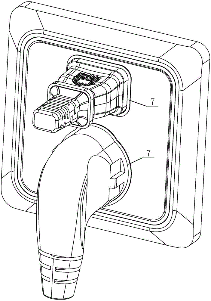
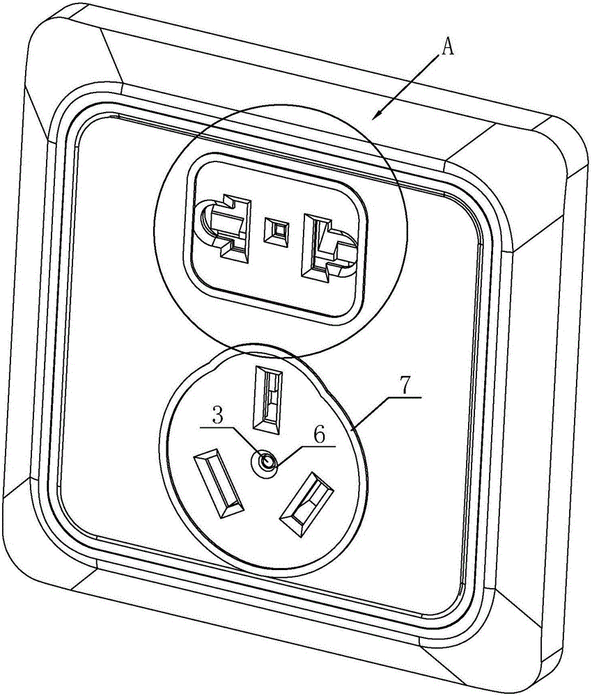
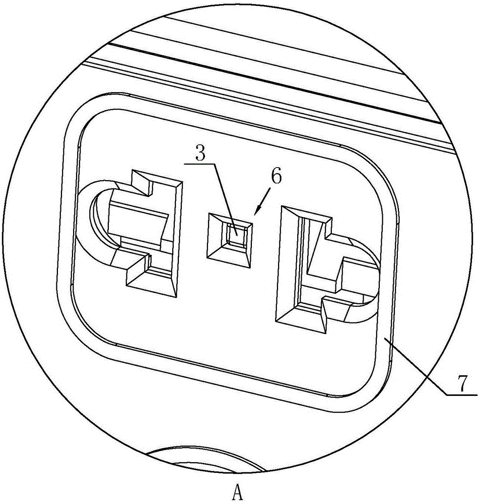
[0043] Such as Figures 1 to 14The bright ring safety socket and plug assembly shown includes a plug and a socket. The socket includes a panel, a jack and a conductive socket. The conductive socket includes a live wire socket and a neutral wire socket. The live wire socket includes a live wire connection plate 40 And live wire slot cover 42, it is characterized in that: the socket periphery is provided with the LED module 7 that can light up when the socket is electrified, and described plug is provided with bump 70, and the panel is provided with the recessed hole that is used for cooperating with bump 70 6. A gap 41 is provided separately between the live wire connecting plate 40 and the live wire slot cover 42 , and the trigger switch assembly 1 for controlling the connection between the live wire connecting plate 40 and the live wire slot cover 42 is provided in the gap 41 .
[0044] The socket includes a conductive socket, the conductive socket includes a live wire socket...
Embodiment 2
[0068] Such as Figure 15 and 16 As shown, the difference between this embodiment and Embodiment 1 is that: the second contact portion 110 is a metal ring with a slope, the slope of the metal ring faces the rear end of the movable contact 31, the convex part 310 is in the shape of a ring, and the movable contact 30 is a circular platform. shape.
[0069] The corresponding effects are as follows: firstly, the annular slope of the metal ring forms a tapered surface, and the second contact portion 110 can increase the contact area with the convex portion 310, effectively avoiding poor contact and improving safety.
[0070] Secondly, the conical surface of the metal ring cooperates with the annular convex portion 310 to make the convex portion 310 concentric with the metal ring to ensure the concentricity of the two, so that the top of the contact can be accurately aligned with the arc-shaped contact portion of the first contact portion 100 1001, to avoid poor contact when misal...
PUM
 Abstract
Description
Claims
Application Information
 - R&D Engineer
- R&D Manager
- IP Professional
- Industry Leading Data Capabilities
- Powerful AI technology
- Patent DNA Extraction
Browse by: Latest US Patents, China's latest patents, Technical Efficacy Thesaurus, Application Domain, Technology Topic, Popular Technical Reports.
© 2024 PatSnap. All rights reserved.Legal|Privacy policy|Modern Slavery Act Transparency Statement|Sitemap|About US| Contact US: help@patsnap.com